
 Engleză
 中文简体
中文简体 Русский
 Español
 Português
 Türkçe
 العربية
 Deutsch
 Polski
 Italiano
 Français
 한국어
한국어 ไทย
ไทย Tiếng Việt
 日本語
日本語





























Generator de căderi și întreruperi de tensiune
Manual de utilizare
Aplicabil LISUN modele: CSS61000-11,CSS61000-11T,CSS61000-11T-100A,CSS61000-11T-32A
1. Despachetarea și familiarizarea de bază cu echipamentul
1.1 Specificații tehnice cheie
| LISUN Model | CSS61000-11 | CSS61000-11T | CSS61000-11T-32A | CSS61000-11T-100A |
| Formă de undă de ieșire | Unda sinusoidală AC | |||
| Intervalul de tensiune | 0–110% of 220 V | 0–110% of 380 V | ||
| Internal IEC Rating | 100%, 80%, 70%, 40%, 0% | |||
| Drop Angle Setting | 0°–360° (in 1° increments) | |||
| Duration of the voltage change | 0.5–9999.5 tone | |||
| Interval between voltage changes | 1 s–9999 ms | |||
| Number of times the voltage changes | 0-9999 ori | |||
| Metode de lucru | Fully Automatic Free-Fall Test | Select any one to three phases that drop simultaneously | ||
| Metoda de declanșare | Manual, Automatic, and 50 ms | |||
| Power Supply for the EUT | Single-phase AC 220 V ±10%, max. 16 A | Three-phase AC 380 V ±10%, max. 20 A per phase | Three-phase AC 380 V ±10%, max. 32 A per phase | Three-phase AC 380 V ±10%, max. 100 A per phase |
| Sursa de alimentare a instrumentului | 220 V c.a. (110 V opțional) ±10%, 50/60 Hz | |||
1.2 Inspecția despachetării și verificarea accesoriilor
1.2.1 Despachetare și inspecție vizuală
When unpacking the device, handle it gently to avoid scratching the casing with sharp tools. After unpacking, first inspect the exterior of the device to ensure there is no obvious deformation or dents, and that the buttons are not damaged or loose.
Dacă observați orice deteriorare sau deformare a echipamentului sau a accesoriilor, nu porniți alimentarea. Vă rugăm să ne contactați imediat.
1.2.2 Unitatea principală și accesoriile
Main Equipment: 1 Voltage Dips and Interruptions Generator.
CSS61000-11 single-phase EUT device looks as follows:
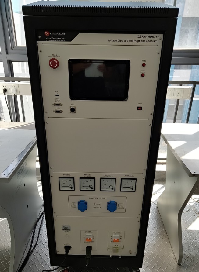
Figura 1
CSS61000-11T three-phase EUT device looks as follows:
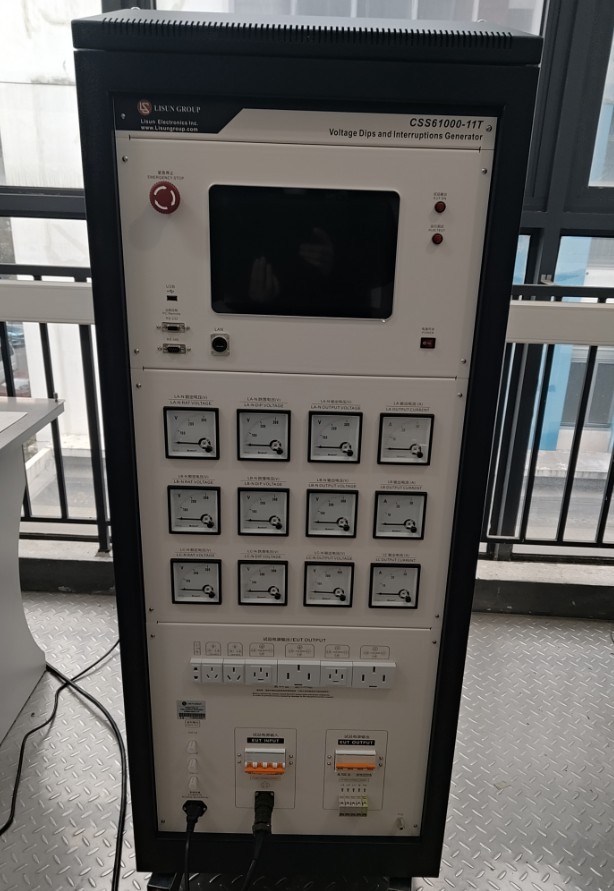
Figura 2
Standard Accessories: ① Equipment power cord; ② EUT (test specimen) input power supply cord; ③ EUT output connection cable; ④ Coaxial cable, which can be connected to an external oscilloscope to view waveforms; ⑤ Ground wire.
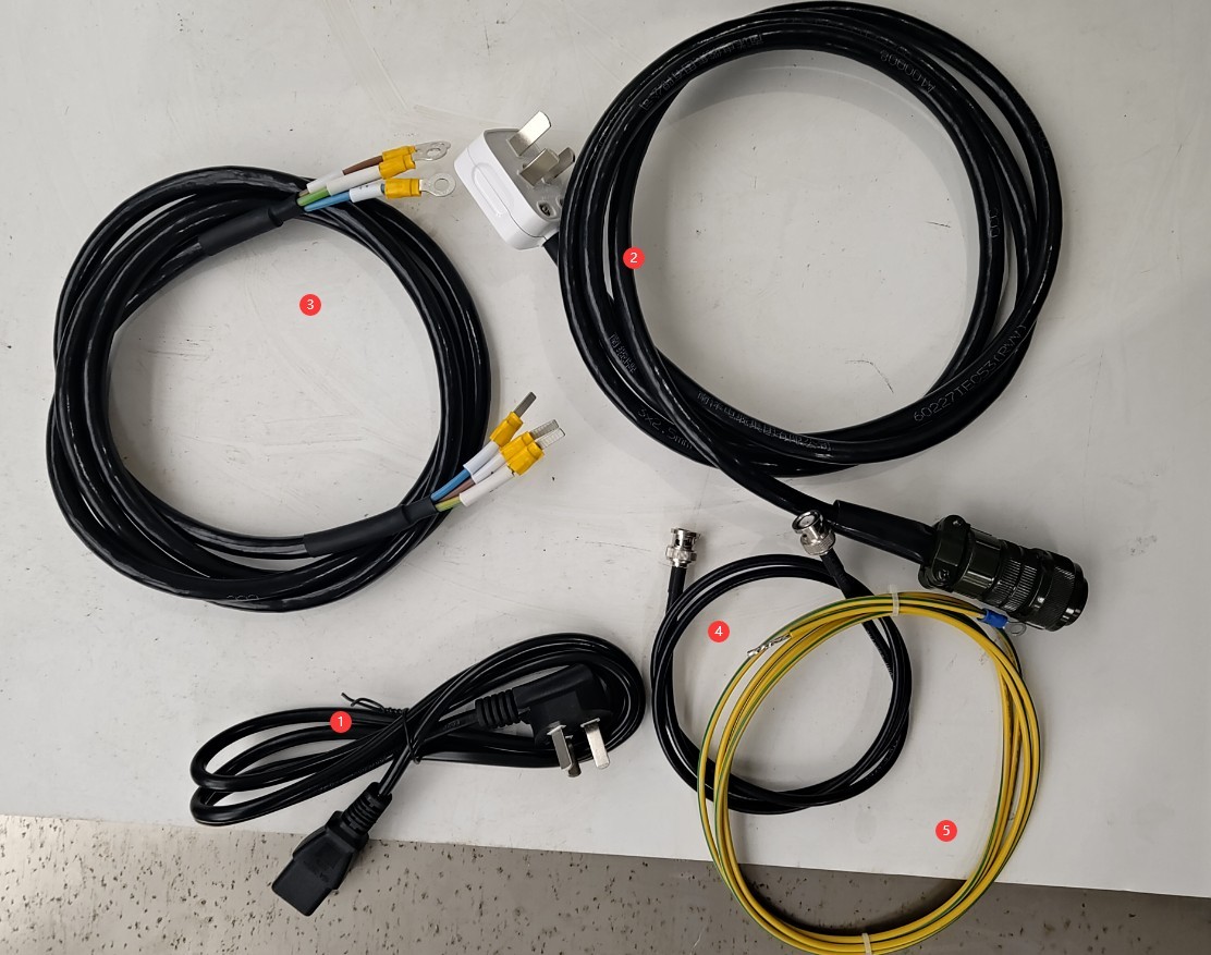
Figura 3
V-au fost trimise prin e-mail linkurile de descărcare pentru manualul de utilizare digital, cardul de garanție și alte documente. Vă rugăm să le descărcați cât mai curând posibil. Dacă ați pierdut e-mailul, nu ezitați să ne contactați pentru a solicita din nou linkurile de descărcare.
2. Măsuri de siguranță
2.1 Ghid de plasare
Asigurați-vă că temperatura ambiantă este între 15°C și 35°C, umiditatea relativă între 30% și 60% (fără condens) și presiunea atmosferică între 86 kPa și 106 kPa pentru a preveni scurtcircuitele de înaltă tensiune sau deteriorarea echipamentului cauzată de umiditate;
The premises must be free of strong electromagnetic interference, corrosive gases, flammable or explosive materials, and dust, and must be well-ventilated;
Așezați-l pe o bancă de lucru stabilă; evitați înclinarea sau răsturnarea lui și țineți-l departe de sursele de vibrații;
The equipment must be placed at least 1000 mm away from walls and surrounding structures (such as other testing equipment and shelving) to facilitate maintenance; at least 2000 mm of space must be left in front of the equipment to ensure smooth operation and keep the surrounding area free of obstructions.
2.2 Standarde de siguranță electrică
2.2.1 Verificare de securitate
Verify that the equipment’s power supply voltage matches the supply voltage, and ensure that the power supply is properly grounded and that the grounding wire is free of damage or looseness.
Grounding Requirements: The protective grounding terminal (PG) on the main unit must be connected to ground, with a grounding resistance of ≤4 Ω.
The EUT’s ground terminal must be at the same potential as the equipment’s grounding system to ensure test safety.
2.2.2 Cerințe de siguranță pentru procedurile operaționale
Operatorii trebuie să urmeze o instruire profesională și să fie familiarizați cu acest manual și cu standardele relevante. Operatorii neprofesioniști au interzisă operarea sau dezasamblarea echipamentului. Echipamentul conține circuite de înaltă tensiune; deschiderea capacului poate prezenta un pericol de electrocutare. Contactați personalul tehnic al producătorului pentru reparații.
While the equipment is in operation, do not touch the EUT’s input and output wires or terminals.
Before switching connections or replacing the EUT, you must first ensure that the EUT’s power input and output switches are turned off.
Când sunt implicate mai multe persoane, definiți clar rolurile și responsabilitățile și confirmați-le reciproc înainte de a începe testul pentru a evita erorile.
2.3 Altele
Pentru aspectele care nu sunt acoperite de acest manual, vă rugăm să procedați cu prudență sau să ne contactați.
3. Pregătiri înainte de test
3.1 Preparation of the EUT (Test Item)
Inspect the EUT to ensure there are no visible damages, no water ingress, and no rust, and that the power connector is intact.
Prepare an external power supply based on the EUT’s rated voltage and current.
3.2 Verification of Standard Parameters
3.2.1 Single-Phase Test Parameters (GB/T 17626.11)
| Nivelul testului | Drop Voltage (relative to UT) | Durată | Scenarii aplicabile |
| Nivel 1 | 80% UT | 10 ms/20 ms/50 ms | Environment with minimal interference |
| Nivel 2 | 70% UT | 10 ms/20 ms/100 ms | General Industrial Environments |
| Nivel 3 | 40% UT | 20 ms/50 ms/200 ms | Medii industriale dure |
| Nivel 4 | 0% UT (Total Drop) | 50 ms/100 ms/500 ms | Extreme Interference Environments |
3.2.2 Three-Phase Test Parameters (GB/T 17626.34)
Drop Type: Single-phase drop, two-phase drop, three-phase drop (select according to test requirements).
Synchronization Requirements: During a three-phase drop, the initial phase difference between phases must be ≤5°, and the duration deviation must be ≤1 ms.
Recovery Requirements: After the drop ends, the voltage recovery time must be ≤ 10 ms, with no overshoot (overshoot voltage ≤ 110% UT).
3.3 Introduction to the Equipment Front Panel and Wiring
① Emergency stop switch; ② USB port, which can be used to connect a mouse or update the software; ③ The remaining three ports are reserved; if not specified at the time of purchase, they have no function;④ Touchscreen; ⑤ EUT power indicator and test indicator; ⑥ Power switch; ⑦ EUT rated voltage display; ⑧ Voltmeter displaying the EUT voltage drop; ⑨ Voltmeter displaying the EUT current voltage; ⑩ Ammeter displaying the EUT current;⑪ Connects to the EUT; ⑫ Connects to the EUT; ⑬ Connects to an external oscilloscope to view the voltage drop waveform; ⑭ Power cord; connect as specified in 2.2.1;⑮ EUT power input terminal; connect to an external power source to supply power to the EUT; ⑯ EUT power input switch; ⑰ EUT connection port; ⑱ EUT power output switch; ⑲ PG protective grounding terminal; connect as specified in 2.2.1; ⑳ EUT test specimen.
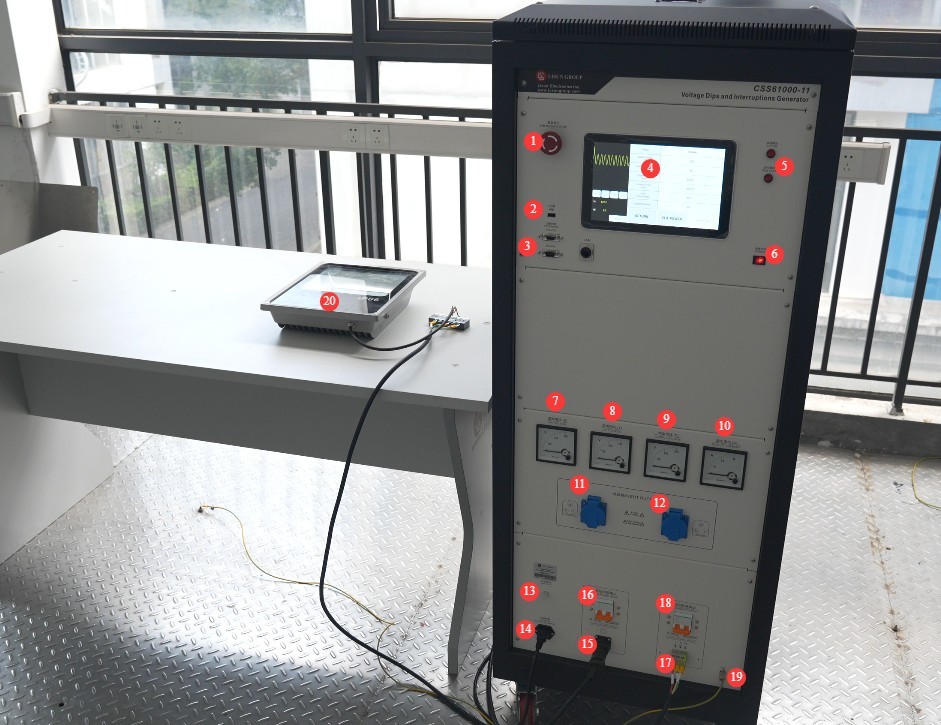
Figura 4
Note: Based on the EUT’s maximum current and for ease of wiring, simply select one of ports ⑪, ⑫, or ⑰ for connection.
3.4 Încălzirea și autotestarea echipamentului
Turn on the power switch on the front panel of the host; the device enters standby mode, the power indicator light turns on, and the cooling fan starts.
Wait 5 minutes for the device to warm up, and check that the touchscreen is displaying normally and that there are no error messages.
4. Introducere în programul cu ecran tactil
4.1 Ecranul inițial
① General Precautions for Use (This feature is still under development; there is no need to access it at this time); ② Switch between Chinese and English; ③ System Information Screen; ④ Voltage and Frequency Dip Test Screen.
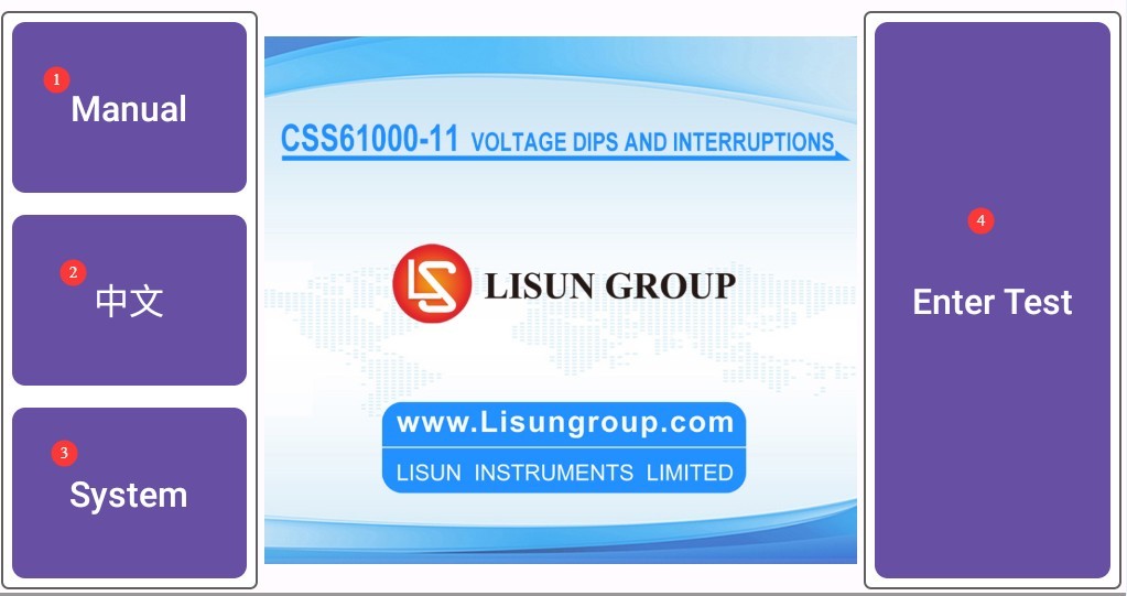
Figura 5
4.2 Ecranul cu informații despre sistem
① Switch the voltage drop mode to perform the voltage drop based on either the rated voltage or the actual voltage. Example: If the rated voltage is 220 V, the actual voltage is 230 V, and the set voltage drop is 160 V, the voltage drop will be 160 V if calculated based on the rated voltage; If the voltage drop is calculated based on the actual voltage, the drop voltage will be 230/(220/160) = 167.3 V.
② Click to view the test log.
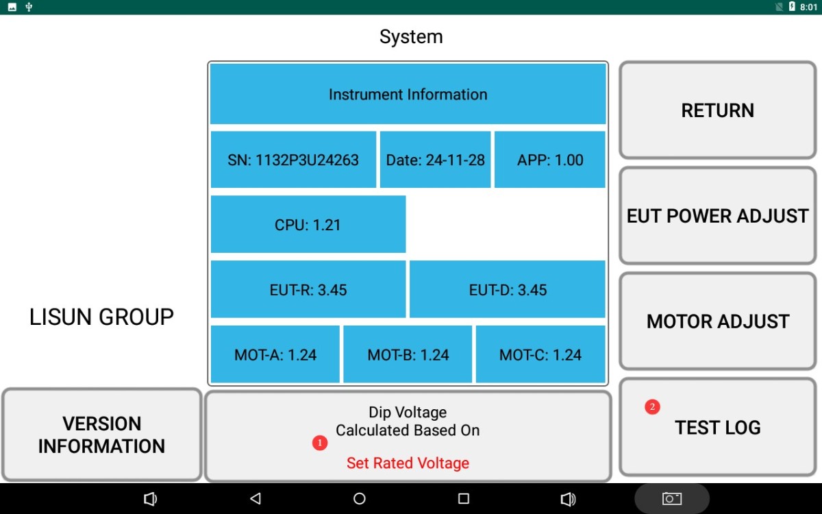
Figura 6
4.3 Interfață de testare
① Voltage waveform display; ② Display of the EUT’s actual voltage and voltage dip; ③ EUT frequency display;④ Special function settings; ⑤ For three-phase EUTs, test parameters can be set separately for each phase (La, Lb, Lc); ⑥ Control whether to perform a voltage dip test on a specific phase; if a dip test is not required for that phase, simply set it to OFF;⑦ Rated voltage setting; ⑧ Voltage dip setting; ⑨ Voltage dip duration setting; ⑩ Interval duration setting; ⑪ Voltage dip phase angle setting; ⑫ Number of voltage dips setting; ⑬ Click to turn the EUT power on or off.
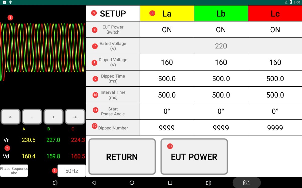
Figura 7
Note 1: For the CSS61000-11 single-phase EUT Voltage Dips and Interruptions Generator, after turning on the EUT input/output switch and setting the rated voltage, the generator will automatically adjust the EUT input power supply to the set rated voltage value based on the setting. The CSS61000-11T three-phase EUT Voltage Dips and Interruptions Generator does not have an automatic rated voltage adjustment function; if you need to adjust the EUT input voltage, you must adjust the external input power supply.
Note 2: If all drop tests are to be conducted at a fixed phase angle: If your EUT sample operates at 50 Hz, set both the drop time and the interval time to be integer multiples of a single cycle (20 ms). If your EUT sample operates at 60 Hz, set both the drop time and the interval time to be integer multiples of a single cycle (16.67 ms). If the set times are not integer multiples of a single cycle, only the first dip may occur at the set phase angle.
Click to enter the special features settings screen (you may choose to enable or disable this feature; it does not affect the test).① Return to the General Settings screen; ② Automatically configure settings according to the electricity meter industry standard; each drop test consists of 3 consecutive drops (spaced 50 ms apart); ③ If your device uses a three-phase circuit for drop testing, click to have Lb and Lc automatically use the settings for La.
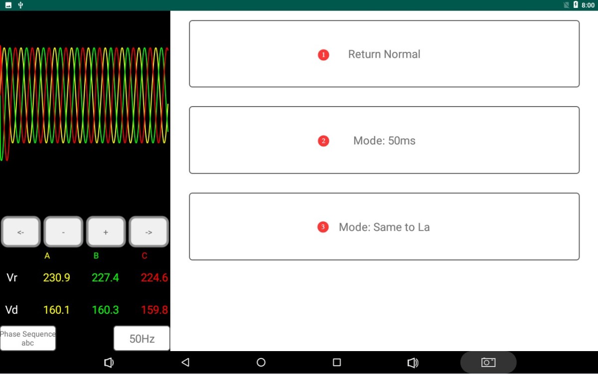
Figura 8
5. Voltage and Frequency Dip Test
5.1 Proceduri Operaționale
Turn on the EUT input power supply switch, and turn on the EUT power output switch.
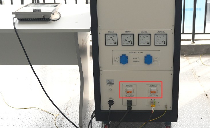
Figura 9
After setting all parameters on the touchscreen interface, the screen displays “Voltage Adjusting.” Observe the rated voltage and voltage dip displays on the screen, as well as the voltmeter reading. When the rated voltage (applicable only to the CSS61000-11 Single-Phase EUT Voltage Dips and Interruptions Generator) and the voltage dip are automatically adjusted to the set values, the prompt disappears.
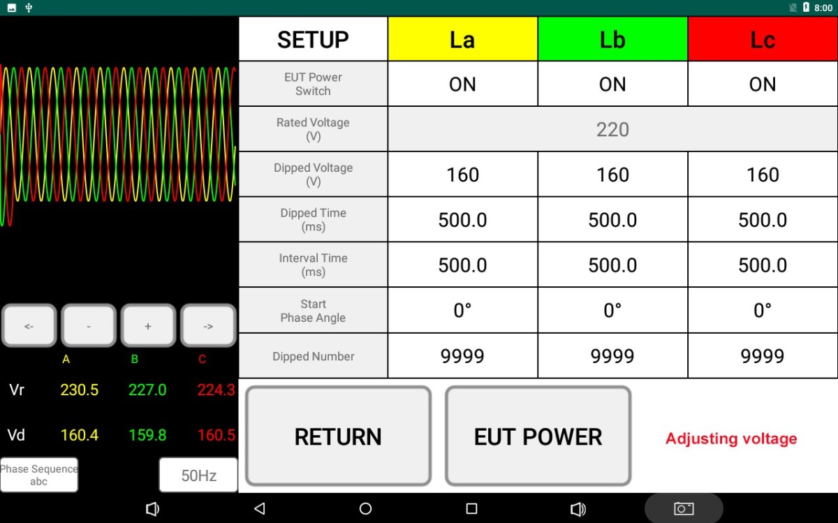
Figura 10
Note: When the above message appears, it indicates that the device is in the process of self-calibration; do not perform any other operations.
Click “EUT POWER” to connect the EUT power supply to the EUT. Follow the instructions in the EUT manual to set it to its normal operating state (e.g., power on and warm up, set the operating mode).
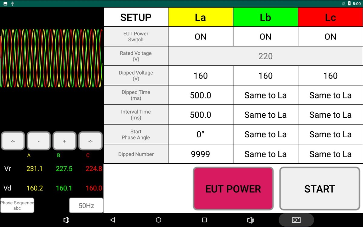
Figura 11
Click “START” to begin the voltage dip test.
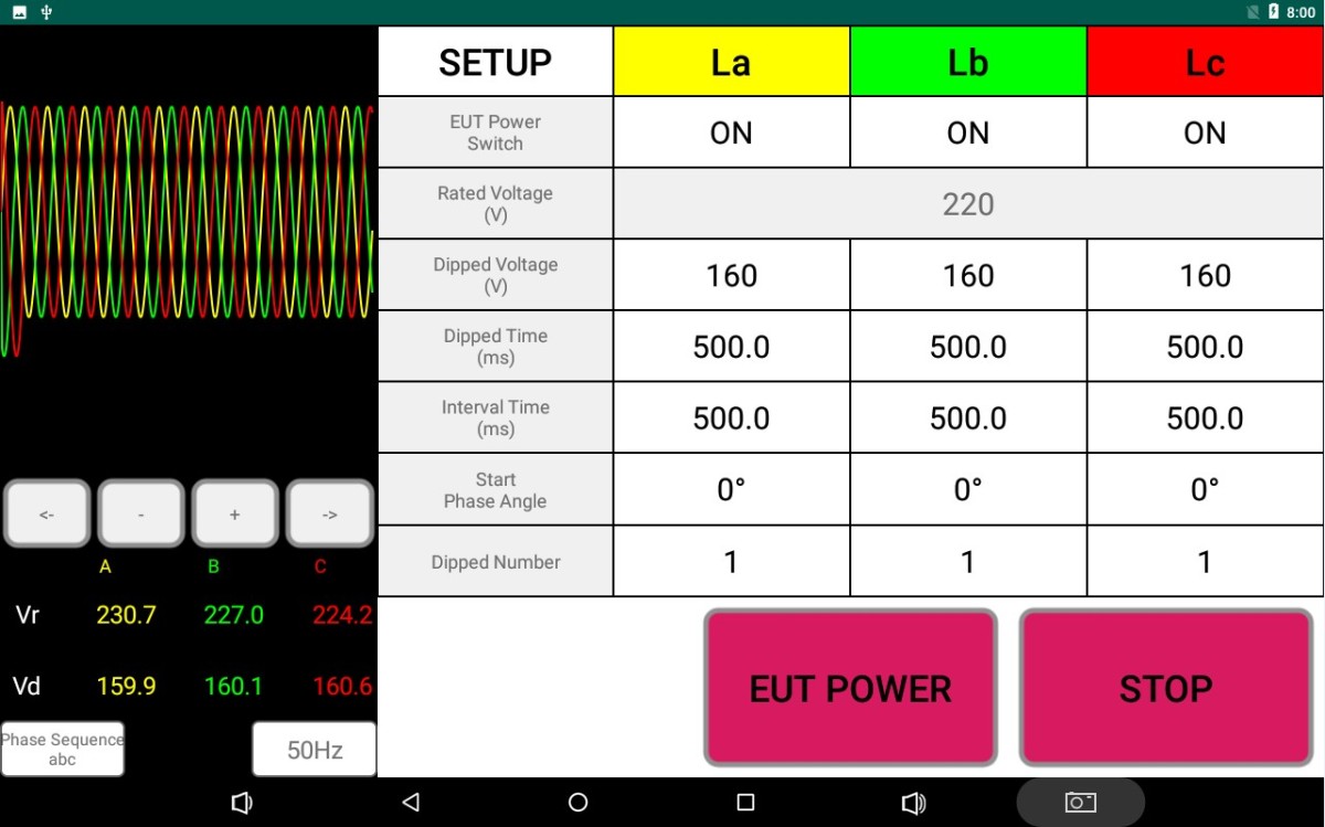
Figura 12
The current voltage and current of the EUT can be monitored, and the display can be switched between the rated values and the test values.
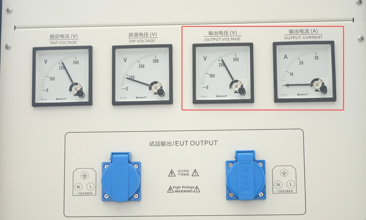
Figura 13
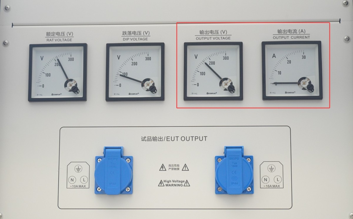
Figura 14
Nota: CSS61000-11 series testers are capable of testing high-power EUTs; the selected current meter is a wide-range current meter. If the EUT current is relatively low, the display may not be clearly visible, but this does not affect the test.
5.2 Determinarea dacă EUT a trecut testul
The four-level performance classification system (A/B/C/D) specified in GB/T 17626.1 (General Principles for Immunity Testing) is adopted.
| Nivel | Definiție | Determination Result |
| PC A | During and after the test, the EUT functioned and performed completely normally, with no abnormalities observed, and complied with the technical specifications set by the manufacturer. | By |
| PC B | Temporary loss of function or temporary degradation in performance may occur during the test; however, once the disturbance ceases, the EUT shall recover to normal operation on its own without operator intervention. | Approved (subject to product specifications) |
| PC C | During testing, a loss of function or reduced performance may occur; while the system cannot recover on its own once the disturbance ceases, it can return to normal through operator intervention (such as resetting, restarting, or reconfiguring), and no permanent damage occurs. | |
| PC D | The EUT has sustained permanent damage, experienced a software failure, or suffered data loss; or its operational metrics or performance deviate from expected values and cannot be restored | Eșua |
GB/T 17626.11-2023 (Equipment ≤ 16 A) Preferred test level:
| Tipul testului | Test Level (Percentage of Residual Voltage) | Durată | Scenarii aplicabile | Recommendation Criteria |
| Scădere de tensiune | 40%, 70% | 0.01 s (half-cycle), 0.1 s, 0.5 s, 1 s | Consumer and commercial electronic devices, small industrial controllers | PC A/B (Use PC A for critical equipment) |
| Short-term interruption | 0% (Completely Interrupted) | 0.001 s (0.05 cycles), 0.01 s, 0.1 s, 1 s | All devices rated at 16A or less | PC B/C (PC B for Critical Equipment) |
| Variația tensiunii | Step Changes: ±10%, ±20% | Sustained and Stable | Voltage-sensitive equipment (such as medical devices and precision instruments) | PC A |
GB/T 17626.34-2012 (Equipment >16A) Preferred Test Level:
| Tipul testului | Test Level (Percentage of Residual Voltage) | Durată | Scenarii aplicabile | Recommendation Criteria |
| Dip de tensiune | 40%, 70% | 0.01 s, 0.1 s, 0.5 s, 1 s, 3 s | Industrial motors, large UPS systems, and power equipment | PC B/C (Use PC B for applications requiring high continuity) |
| Brief interruption | 0% | 0.01 s, 0.1 s, 1 s, 3 s, 10 s | Industrial automation systems, large-scale refrigeration equipment | PC C (PC C may be accepted in special circumstances) |
| Fluctuații de tensiune | Step changes: ±10%, ±20% | Sustained and Stable | Power Supplies for Large-Scale Industrial Control Systems and Data Centers | PC A/B |
6. Proceduri post-test
6.1 Emergency Stop Procedure
6.1.1 Conditions for Triggering an Emergency Stop
The EUT presents serious safety hazards, such as smoke, fire, or explosion.
The equipment exhibits abnormal noises, odors, or overheating (casing temperature exceeds 60°C).
Loose terminal connections and short circuits caused the equipment to trip.
6.1.2 Proceduri de răspuns în caz de urgență
Immediately press the emergency stop switch (red; rotate clockwise to reset), and all power to the equipment will be cut off.
If the EUT catches fire, use a dry-powder fire extinguisher to put out the fire (never use water).
Once the equipment has cooled down, check for the cause of the malfunction (e.g., wiring, parameters, EUT status).
After troubleshooting, turn the “Emergency Stop” button to reset it, and restart the equipment following the normal wiring and startup procedures.
6.2 Procedure for Concluding a Normal Test
6.2.1 Testing Complete
The test is complete, and the device has entered standby mode.
6.2.2 Power Disconnection and Disconnection of Wires from the EUT
Turn off the EUT in the following order: Click “EUT POWER” to cut off power to the EUT, turn off the EUT power output switch, and turn off the EUT power input switch.
Replace the EUT for testing, or turn off the device’s power.
6.3 Curățenie și organizare post-test
Curățați zona de testare și ștergeți-o cu o cârpă uscată. Nu utilizați alcool sau agenți de curățare corozivi.
6.4 Depozitarea echipamentelor
6.4.1 Cerințe privind depozitarea pe termen scurt
Dacă echipamentul este utilizat zilnic, nu este necesară nicio altă acțiune după finalizarea curățării în urma fiecărui test.
6.4.2 Cerințe pentru depozitarea pe termen lung
Dacă dispozitivul nu va fi utilizat pentru o perioadă lungă de timp (mai mult de o lună), deconectați toate cablurile și acoperiți dispozitivul cu o husă de praf pentru a preveni acumularea de praf.
Dispozitivul trebuie pornit o dată pe lună, timp de doar o jumătate de oră, pentru a preveni îmbătrânirea componentelor electrice (cum ar fi condensatoarele și contactoarele).
7. Depanarea și rezolvarea problemelor comune
7.1 Symptom: The device does not respond after power-on (the indicator light does not come on, and the fan does not spin)
Possible causes: The power cord is not properly connected or is damaged; abnormal supply voltage; a blown fuse; a blown varistor (MOV).
Troubleshooting: Ensure the power cord is intact and securely connected. Power supply issues—such as unstable voltage, excessively high voltage, or harmonic interference—can cause the fuse or varistor to burn out. We recommend using a voltage-stabilized, pure sine wave AC power supply to power the device. Replace the fuse or varistor with one of the same type.
The figure below shows the location of the fuse:
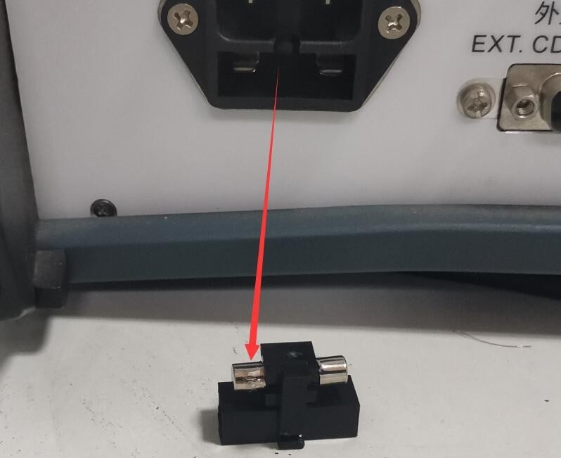
Figura 39
Figura de mai jos arată locația varistorului (MOV) în interiorul sursei de alimentare filtrate:
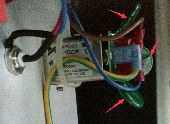
Figura 40
7.2 Symptom: The circuit breaker trips immediately after startup
Possible causes: Short circuit in the EUT; short circuit between the EUT input and output conductors
Troubleshooting: Check whether the EUT’s input/output wires are exposed or shorted, and replace any damaged cables; check whether the EUT is shorted (measure the resistance at the EUT’s power input terminals with a multimeter); after resolving the EUT fault, try again.
7.3 Symptoms: The “(START) Start Test” button cannot be activated
Possible causes: The voltage has not been adjusted properly; the EUT has not been powered on.
Solution: Wait 3 to 5 seconds to allow the device to automatically adjust the voltage to the set value (wait until the Vr and Vd readings stabilize); click the “EUT Power” button to power on the EUT, then try again.