
 Engleză
 中文简体
中文简体 Русский
 Español
 Português
 Türkçe
 العربية
 Deutsch
 Polski
 Italiano
 Français
 한국어
한국어 ไทย
ไทย Tiếng Việt
 日本語
日本語





























Dulap de încărcare pentru lămpi cu tungsten/halogen
Manual de utilizare
Aplicabil LISUN models: DFX-WD20A
1. Despachetarea și familiarizarea de bază cu echipamentul
1.1 Specificații tehnice cheie
1.1.1 DFX Tungsten Filament Lamp Load Cabinet
Power Supply: Single-phase AC 220 ± 10% / 50 Hz with ground wire;
Digital Voltmeter: Range 0–300 V, accuracy ±0.5% ±2d;
Digital ammeter: Range 0–40 A, accuracy ±0.5% ±2d;
Digital Power Meter: Range 0–9 kW, Accuracy ±0.5% ±2d;
Load Configuration: Built-in 3 sets of multi-bulb 200W tungsten/halogen lamp combinations, with cyclic power supply;
Number of output channels: 1;
Load capacity: 7.5 kVA;
The maximum output current is 20 A; the load is automatically disconnected when the current exceeds 22 A;
The maximum output voltage is 300 V; when it exceeds 305 V, the load is automatically disconnected;
Selecting the number of tungsten filament lamps/halogen lamps: Each lamp has a power rating of 200 W, available in sets of 1, 2, 3, 4, 10, or 10 lamps;
Counter: Preset range of 0 to 999999;
Features a long-stick protection function: The upper limit for long-stick time can be preset from 0 to 99 seconds.
1.1.2 CZKS Series Socket and Switch Life Test Machine
| LISUN Model | CZKS-3 | CZKS-3P | CZKS-3S | CZKS-3A |
| Stații de lucru | 2 Outlets + 1 Switch | 3-outlet outlet | Comutatoare 3 | 1 Outlet + 2 Switches |
| Tipul de unitate | Pneumatic drive; customer-supplied air source: 0.8 MPa | |||
| Metode de control | PLC + Extra-Large Touchscreen | |||
| Timp de pornire/oprire | 0–99.9 seconds per minute (adjustable) | |||
| Numărul de teste | 0–999999 times (preset) | |||
| Run Test | Linear: -40 to 110 mm (presettable); Rotation: 0 to 360° (presettable) | |||
| Rata de testare | Linear: 0–100 mm/s (preset); Rotational: 0–90°/s (preset) | |||
| Eșantion de fixare | Comes standard with a universal clamp that can be adjusted up and down (other special clamps can be custom-made according to customer requirements) | |||
| LISUN Model | CZKS-6 | CZKS-6P | CZKS-6S | CZKS-6X |
| Stații de lucru | 3 Outlets + 3 Switches | 6-outlet outlet | Comutatoare 6 | Custom Number of Outlets + Switches |
| Tipul de unitate | Pneumatic drive; customer must provide their own air supply: 0.8 MPa | |||
| Metode de control | PLC + Extra-Large Touchscreen | |||
| Timp de pornire/oprire | 0–99.9 seconds per minute (adjustable) | |||
| Numărul de teste | 0–999999 times (preset) | |||
| Run Test | Linear: -40 to 110 mm (presettable); Rotation: 0 to 360° (presettable) | |||
| Rata de testare | Linear: 0–100 mm/s (preset); Rotational: 0–90°/s (preset) | |||
| Eșantion de fixare | Comes standard with a universal clamp that can be adjusted up and down (other special configurations can be customized according to customer requirements) | |||
1.2 Inspecția despachetării și verificarea accesoriilor
1.2.1 Despachetare și inspecție vizuală
Când despachetați dispozitivul, manipulați-l cu grijă pentru a evita zgârierea carcasei cu unelte ascuțite. După despachetare, inspectați mai întâi exteriorul dispozitivului pentru a vă asigura că nu există deformări sau lovituri vizibile și că butoanele nu sunt deteriorate sau slăbite.
Dacă observați orice deteriorare sau deformare a echipamentului sau a accesoriilor, nu porniți alimentarea. Vă rugăm să ne contactați imediat.
1.2.2 Unitatea principală și accesoriile
Load cabinet: 1 unit; CZKS life tester: 1 unit.
Standard accessories: 200W tungsten bulbs—52 in total (32 for the load cabinet, with the remaining 20 as spares).
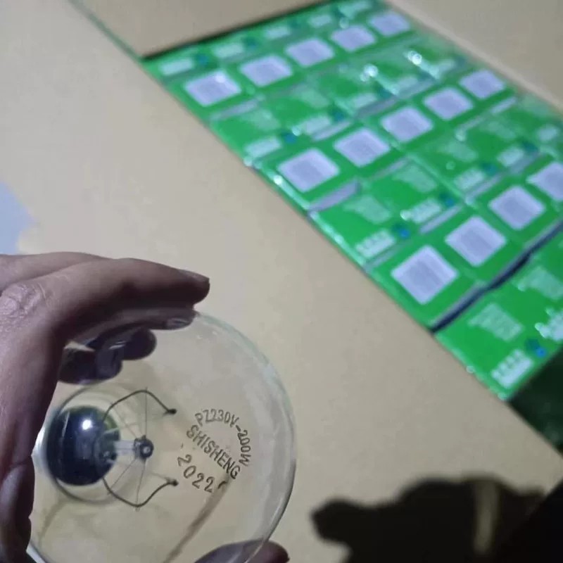
Figura 1
Nota: LISUN switch life tester must be used in conjunction with an air compressor. Users may purchase one from LISUN or provide their own. If providing your own, please ensure it is capable of delivering compressed air at 0.8 MPa. An air hose with an 8 mm outer diameter is required for connection to the switch life tester.
V-au fost trimise prin e-mail linkurile de descărcare pentru manualul de utilizare digital, cardul de garanție și alte documente. Vă rugăm să le descărcați cât mai curând posibil. Dacă ați pierdut e-mailul, nu ezitați să ne contactați pentru a solicita din nou linkurile de descărcare.
1.3 Descrierea structurii echipamentului
1.3.1 Load Cabinet
Front of the load cabinet:
① Load (tungsten filament lamp) voltage display; ② Load current display; ③ Load power display; ④ Number of tests: the top line shows the current number of tests performed, and the bottom line shows the set total number of tests;⑤ Long-duration stick-on protection time: the top line shows the current load on-time, and the bottom line shows the set long-duration stick-on time. Once the load’s single on-time reaches the set long-duration stick-on time, the load cabinet will sound an alarm and automatically cut off the output; ⑥ Load cabinet power switch; ⑦ Load power switch;⑧ Tungsten filament lamp quantity selector switch; combinations can be freely configured as needed; ⑨ Enable load output; ⑩ Disable load output; ⑪ Load on/off indicator light / Alarm reset button; ⑫ Alarm; ⑬ Cooling fan switch; ⑭ Load voltage adjustment dial.
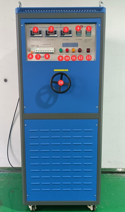
Figura 2
Left side and interior of the load cabinet:
① Tungsten filament lamp mounting slots—please install tungsten filament lamps in all 32 slots before use; ② Cooling fan; ③ Power cord for the load cabinet.
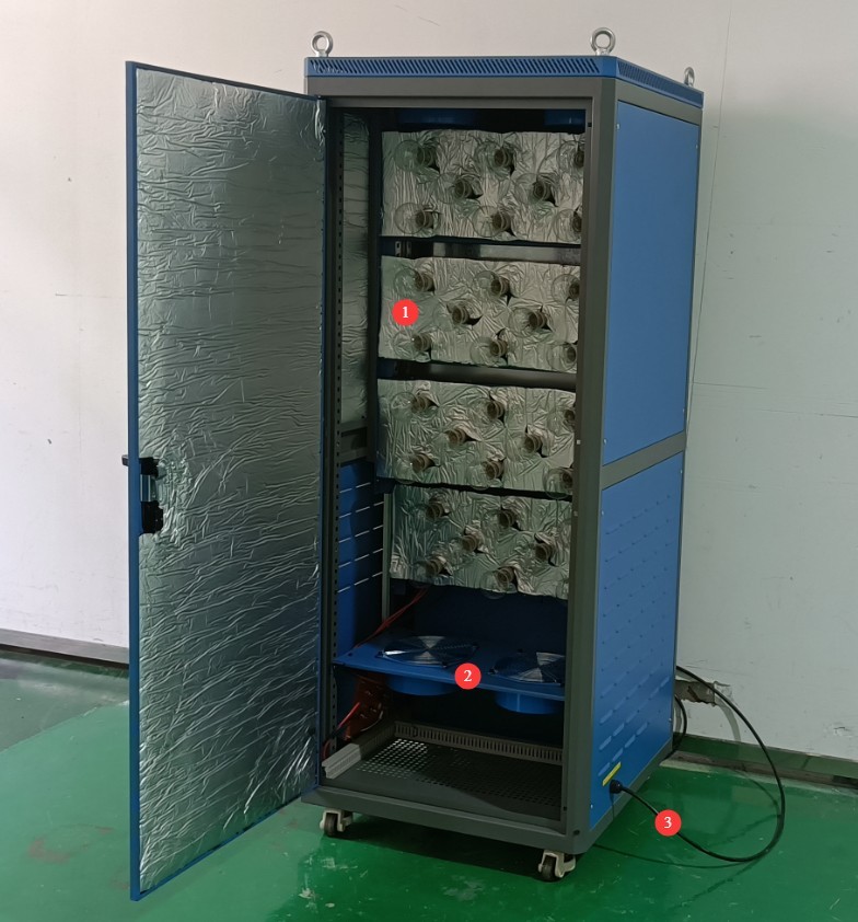
Figura 3
Right side of the load cabinet:
① The three terminals on the left are used to connect a separate power supply to power the tungsten filament lamp; ② The four terminals on the right are used to connect to the switch life tester and the test switch.
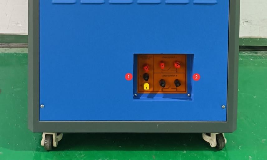
Figura 4
1.3.2 Life Test Machine
The life test machines are available in two series: the 3-station CZKS-3 and the 6-station CZKS-6. There are two types of fixtures: fixtures for testing sockets and fixtures for testing switches. Taking the CZKS-6 model as an example:
① Touchscreen; ② Power switch; ③ Switch fixture; ④ Outlet fixture; ⑤ Terminal block; ⑥ Circuit breaker; ⑦ Power cord receptacle; ⑧ Air compressor connection.
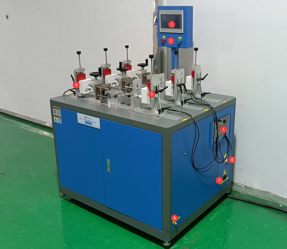
Figura 5
2. Măsuri de siguranță
2.1 Siguranța electrică
2.1.1 Conexiune la alimentare
Alimentare monofazată de 220 V; prizele trebuie să respecte standardele de siguranță, să aibă o împământare corespunzătoare și un curent nominal care să corespundă cu puterea nominală a echipamentului.
Note: The load cabinet itself does not have a high power rating; its maximum current is less than 1 A. However, tungsten filament lamps draw a significant amount of power when in operation. Please check the nameplate and the markings on the terminal blocks, and select a suitable power supply.
2.1.2 Specificații de împământare
The equipment must be reliably grounded, with a grounding resistance of ≤4 Ω. Do not use gas pipes, non-metallic water pipes, or neutral wires as substitutes for the grounding wire. After grounding is complete, use a Grounding Resistance Tester to measure the grounding resistance. Power may only be applied after confirming that the requirements are met, to prevent electric shock, equipment malfunctions, or measurement errors caused by poor grounding.
2.2 Siguranța operațională
Înainte de a cabla, inspecta sau întreține echipamentul, trebuie să opriți întrerupătorul de alimentare al echipamentului și sursa principală de alimentare și să confirmați că nu există tensiune reziduală înainte de a continua;
Nu acționați comutatorul de alimentare, ecranul tactil sau butoanele instrumentului cu mâinile ude pentru a evita riscul de electrocutare;
Nu așezați obiecte străine (cum ar fi unelte sau hârtie) în interiorul tabloului de comandă electric pentru a preveni ca praful sau obiectele străine să provoace scurtcircuite sau să deterioreze componentele;
Do not plug in or unplug power cords or signal cables while the equipment is running, to prevent short circuits that could damage the controller or electrical components.
2.3 Siguranța mediului
Echipamentul trebuie amplasat într-un mediu uscat, fără gaze corozive și materiale inflamabile sau explozive.
Echipamentul trebuie instalat într-o încăpere climatizată, cu temperatura ambiantă menținută între 5°C și 35°C și umiditatea relativă ≤ 85%.
Distanța dintre echipament și pereți, precum și structurile înconjurătoare (cum ar fi alte echipamente de testare și rafturi), trebuie să fie de cel puțin 1000 mm pentru a facilita întreținerea; în fața echipamentului trebuie lăsat un spațiu de cel puțin 2000 mm pentru a asigura o funcționare fără probleme și pentru a menține zona înconjurătoare liberă de obstacole;
Echipamentul trebuie așezat pe o suprafață plană și stabilă; înălțimea picioarelor echipamentului este reglabilă.
2.4 Altele
Pentru aspectele care nu sunt acoperite de acest manual, vă rugăm să procedați cu prudență sau să ne contactați.
3. Introduction to the Touchscreen Program for the Life Test Machine
3.1 Work Page
① Manual/Automatic Switch; ② Start/Stop Test; ③ Station List.
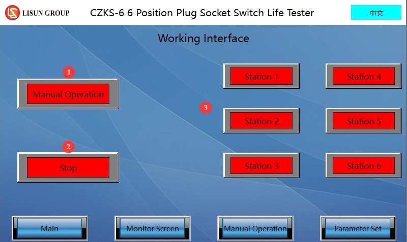
Figura 6
3.2 Parameter Settings Page
① Page navigation; ② Total number of tests; ③ Load on time; ④ Load off time; ⑤ Number of failed current monitoring attempts; ⑥ Whether current is being monitored.
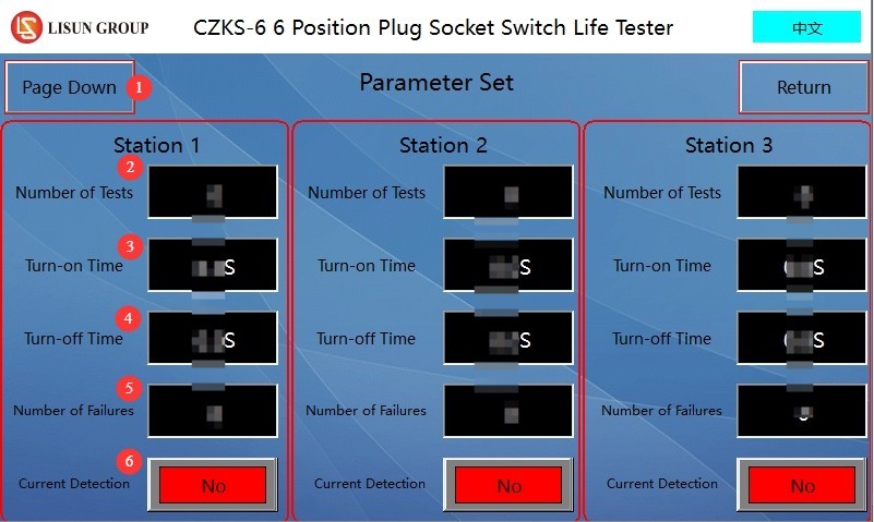
Figura 7
Note: Users can set different parameters for different workstations.
3.3 Fereastra Manuală
Click the manual control button for the corresponding workstation to manually adjust the position of the fixture at that workstation.
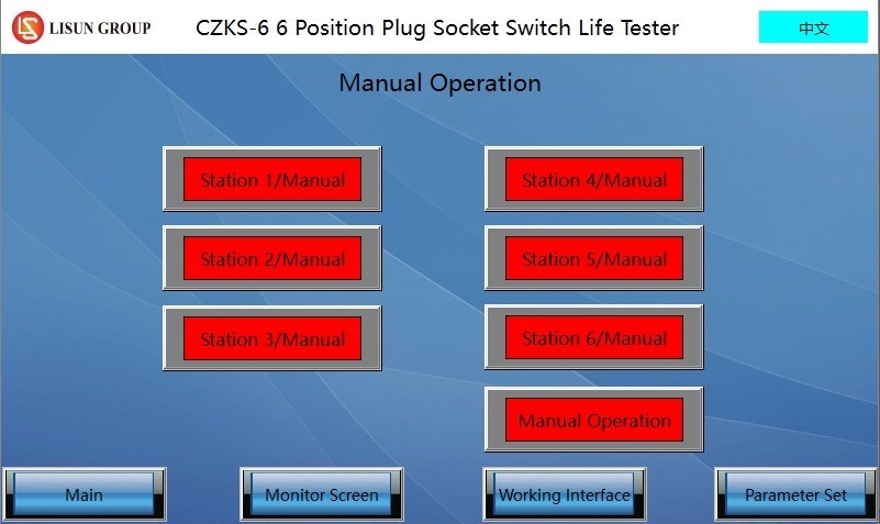
Figura 8
3.4 Surveillance Footage
① Page navigation; ② Run/Pause; ③ Monitor current; ④ Total number of tests; ⑤ Number of tests performed; ⑥ Number of current monitoring sessions; ⑦ Reset.
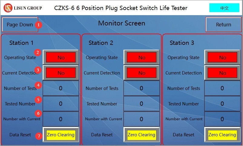
Figura 9
4. Pregătiri înainte de test
4.1 Cablajul echipamentului
4.1.1 Conectarea cablului de alimentare
Please refer to Chapter 2. Turn on the life-cycle tester; do not turn on the load cabinet at this time.
4.1.2 Conectarea compresorului de aer
Connect an air hose with an outer diameter of 8 mm to the endurance testing machine, then turn on the air compressor.
4.1.3 Connecting the Load Cabinet, Endurance Tester, and Specimen
The load cabinet has the following four terminals—two red and two black—as shown in the figure below.
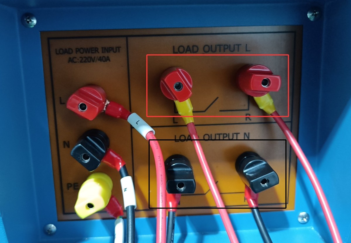
Figura 10
4.1.3.1 Single-Pole Switch
Connect the two red terminals or the two black terminals of the load cabinet to the life tester, and then short-circuit the other two terminals.
The two terminals on the load cabinet are connected to terminals A and B on the life testing machine, and terminals A and C on the life testing machine are connected to the sample switch, as shown in the wiring diagram for workstation 4 of the life testing machine below.
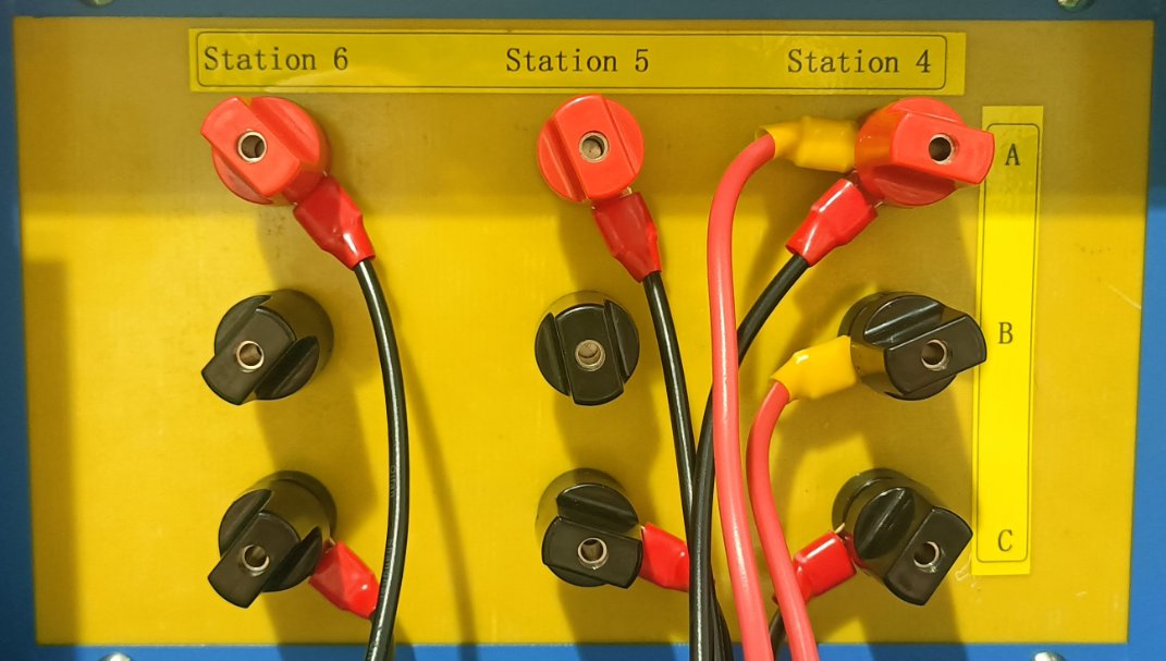
Figura 11
4.1.3.2 Dual-Control Switch
Connect the two terminals on the load panel that are short-circuited directly to one circuit of the double-pole switch, and then connect the other circuit of the double-pole switch as described in section 4.1.3.1.
4.2 Sample Calibration
Open the manual window of the life test machine. Click the button for the corresponding test station to perform a single-cycle operation, then observe the position of the machine’s actuators. If the test specimen is a switch, adjust the machine so that when the upper actuator extends, it just closes the switch, and when the lower actuator extends, it just opens the switch.
After debugging is complete, the switch should be set to the off position.
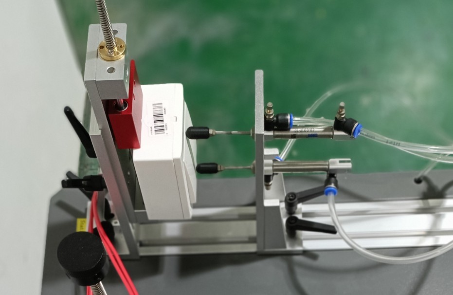
Figura 12
5. Switch Life Test Procedure
5.1 Configurarea dulapului de încărcare
Turn on the power switch for the load cabinet.
The number of test cycles is factory-set to 9999, and the adhesive holding time is factory-set to 90 seconds. Users can also adjust these settings as needed.
Turn on the load cabinet’s power switch, press the “Start Load Output” button, and turn on all cooling fans.
Slowly rotate the voltage adjustment dial while monitoring the test voltage until the voltage meets the test specifications. Note: When the load voltage exceeds 305 V, the device will automatically disconnect the load.
Turn on the tungsten filament lamp quantity selector switch as needed; with a maximum load of 30 tungsten filament lamps (if switches 1, 2, 3, 4, 10, and 10 are all turned on, the total number of tungsten filament lamps in use is 1 + 2 + 3 + 4 + 10 + 10 = 30). Users may also freely combine switches according to their needs.
Example: According to Clause 18.3 of standard GB/T 16915.1-2024 (IEC 60669-1:2017, Clause 18.3), when testing a 10 A, 250 V switch, the voltage required for a 200 W tungsten filament lamp is 240 V, and 15 such lamps are required.
In the manual window of the life test machine, turn on the switch for the corresponding workstation. See the figure below:
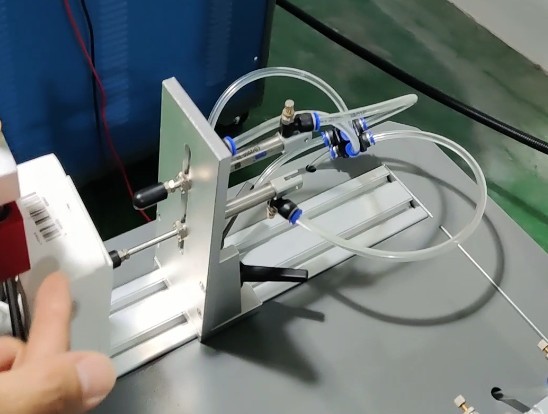
Figura 13
After the switch is turned on, the voltage will drop slightly, requiring you to turn the voltage adjustment knob again. At this point, the test load current is 1.2 times the rated current of the sample switch, or approximately 12 A. Note: When the load current exceeds 22 A, the load cabinet will automatically disconnect the load.
Once the adjustment is complete, go to the manual control panel of the endurance tester and return the specimen to its original state by setting the specimen switch to the “OFF” position.
5.2 Setting Up the Life Test Machine
Parameter Settings Interface. For each workstation, configure the total number of tests, load on time, load off time, number of failed current monitoring attempts, and whether to monitor current.
Note 1: The number of faults refers to the number of times the sample was energized but no current was detected (the test will automatically stop once the actual number of faults during the test reaches the set fault limit; this parameter is invalid when current monitoring is disabled);
Note 2: Current monitoring should only be enabled when a load cabinet is connected to that test station for testing.
Monitoring Interface. Used to view the test status and data for the corresponding workstation. Please click the “Reset” button for the corresponding workstation to clear the previous test data before you can begin testing at that workstation.
5.3 Life Test
5.3.1 Pornirea testului
Go to the work interface. ① Select the workstation you want to run, ② click to switch from manual to automatic, ③ click to start the test.
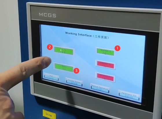
Figura 14
5.3.2 Monitorizarea testelor
During the test, you can view real-time data on the monitoring screen.
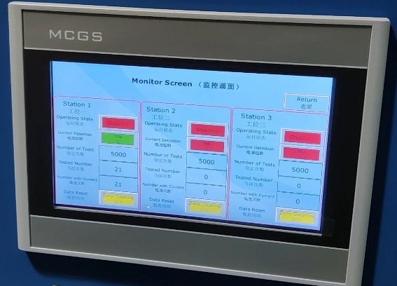
Figura 15
5.3.3 Sfârșitul testului
If the number of test cycles at a life test machine station reaches the set limit, that station will stop the test and automatically place the specimen in the disconnected state. Important note: The load cabinet is still outputting power; please turn off the load output before proceeding.
If the life tester station is equipped with selective current monitoring and the number of failures during the test reaches the preset limit, the life tester will automatically stop the test at that station and automatically disconnect the test specimen. Important Note: The load cabinet will still be in the output state; please turn off the load output before proceeding with any further operations.
If a sample at a test station on the life tester is damaged during testing and remains in the “always on” state, the load cabinet will trigger an alarm after the load has been continuously applied for 90 seconds and will automatically cut off the output. Please press the alarm reset button on the front panel of the load cabinet and manually end the test for the corresponding station on the life tester.
6. Proceduri post-test
6.1 Viewing Recorded Test Data
Access the life test machine monitoring screen, check and record the test data for each station.
6.2 Închidere
Turn off the air compressor;
Turn off the life-cycle testing machine;
Disconnect the load output from the load cabinet, turn off the cooling fan, reset the tungsten lamp quantity selector switch to its original position, and turn off the power to the load cabinet.
6.3 Check the Sample Condition
Use a screwdriver to loosen the clamp screws, remove the tested sample, inspect the sample’s appearance (e.g., check for deformation of the socket and plug, or ablation of the switch contacts), and record the test results.
7. Întreținerea și îngrijirea zilnică a echipamentelor
7.1 Curățarea și întreținerea
After the test is complete, wipe down the life-test machine fixtures and other components with a dry cloth; do not use corrosive cleaning agents. Remove dust from the equipment’s terminal blocks to prevent poor contact.
7.2 Lubrifiere și întreținere
Apply lubricating oil to the sliding components of the endurance testing machine (slide rails, cylinder piston rods) to ensure smooth mechanical operation; check the fixture screws and tighten any loose parts promptly.
7.3 Depozitarea echipamentelor
7.3.1 Cerințe privind depozitarea pe termen scurt
Dacă echipamentul este utilizat zilnic, nu este necesară nicio altă acțiune după finalizarea curățării în urma fiecărui test.
7.3.2 Cerințe privind depozitarea pe termen lung
Dacă dispozitivul nu va fi utilizat pentru o perioadă lungă de timp (mai mult de o lună), deconectați toate cablurile și acoperiți dispozitivul cu o husă de praf pentru a preveni acumularea de praf.
Dispozitivul trebuie pornit o dată pe lună, timp de doar o jumătate de oră, pentru a preveni îmbătrânirea componentelor electrice (cum ar fi condensatoarele și contactoarele).
8. Depanarea și rezolvarea problemelor comune
8.1 Failures in Life Testing Machines
8.1.1 The testing machine has no mechanical movement
Causes of malfunction: Insufficient air supply pressure < 0.8 MPa, air leak at the air supply connection, or malfunction of the cylinder solenoid valve;
Solution: Adjust the air compressor pressure to 0.8 MPa, replace the leaking air supply hose, and contact the manufacturer to repair the solenoid valve.
8.1.2 No Display on the Touchscreen / Touchscreen Not Responding
Causes of the malfunction: Power not connected, loose touchscreen ribbon cable, PLC program error;
Troubleshooting: Check the power connections on the testing machine and firmly reconnect the touchscreen ribbon cable. If there is a software error, contact the manufacturer for assistance.
8.1.3 The Workstation Fails to Start
Cause of failure: Current monitoring failure, short circuit in the sample wiring, or the number of tests or failures has reached the preset value;
Solution: Check the sample wiring, click the “Reset” button on the monitoring screen, and replace the current detection module if it is damaged.
8.2 Load Cabinet Failure
8.2.1 No Voltage/Current Output
Causes of malfunction: Main power not turned on, voltage knob not adjusted, loose terminal connections;
Procedure: Turn on the main power supply to the load cabinet, adjust the voltage knob to the rated value, and tighten the terminal screws.
8.2.2 Abnormal Display in the Electrical Parameters Table
Causes of malfunction: Corrupted parameter table, stuck voltage dial, poor sample contact;
Solution: Replace the electrical parameter meter, remove any debris from the turntable, and reinstall the sample to ensure proper contact.
8.2.3 Continuous Equipment Alarms
Causes of malfunction: Sample current remains active for more than 90 seconds, load overload, or a malfunctioning alarm reset button;
Troubleshooting: Check for a short circuit in the sample, reduce the load current to the rated value, and replace the alarm reset button.
8.3 Joint Test Failures
Failure Symptom: Frequent failures of test specimens during electrical life testing
Cause of the malfunction: Load parameters do not meet standard requirements; deviation in the sample installation position;
Solution: Readjust the current and power factor of the load cabinet to the standard values, and adjust the mechanical position of the testing machine to ensure good contact with the sample.