Engleză
 中文简体
中文简体 Русский
 Español
 Português
 Türkçe
 العربية
 Deutsch
 Polski
 Italiano
 Français
 한국어
한국어 ไทย
ไทย Tiếng Việt
 日本語
日本語





























Cameră de temperatură înaltă și joasă
Manual de utilizare
Aplicabil LISUN models: GDJW-013A、GDJW-013B、GDJW-013C、GDJW-013D、GDJW-015A、GDJW-015B、GDJW-015C、GDJW-015D、GDJW-020A、GDJW-020B、GDJW-020C、GDJW-020D、GDJW-100A、GDJW-100B、GDJW-100C、GDJW-100D、GDJW-225A、GDJW-225B、GDJW-225C、GDJW-225D、GDJW-500A、GDJW-500B、GDJW-500C、GDJW-500D、GDJW-800A、GDJW-800B、GDJW-800C、GDJW-800D
1. Noțiuni de bază despre echipament
1.1 Specificații tehnice cheie
| LISUN Model | GDJW-100* | GDJW-225* | GDJW-500* | GDJW-010* | GDJW-015* | GDJW-020* |
| Dimensiuni compartiment de lucru (cm) | × × 41 55 45 | × × 50 60 75 | × × 70 80 90 | × × 100 100 100 | × × 100 100 150 | × × 100 100 200 |
| Interval de temperatură | A: -20°C până la 150°CB: -40°C până la 150°CC: -60°C până la 150°CD: -70°C până la 150°C | |||||
| Variabilitate/Uniformitate | ±0.5°C/±2°C | |||||
| Rata de creștere a temperaturii | 1.0°C până la 3.0°C pe minut | |||||
| Rata de racire | 0.7°C până la 1.0°C pe minut | |||||
1.2 Despachetarea și verificarea conținutului
1.2.1 Despachetare și inspecție vizuală
When unpacking the equipment, handle it gently to avoid scratching the exterior casing with sharp tools. After unpacking, first inspect the exterior of the main unit to ensure there is no visible deformation, dents, or peeling paint, and that the panel instruments and buttons are not damaged or loose. If you discover any damage or deformation to the equipment or accessories, do not power it on. Contact LISUN serviciu pentru clienți imediat.
1.2.2 Host-type
1 High and Low Temperature Chamber.
1.2.3 Consumabile și accesorii
Deschideți cutia de accesorii. Accesoriile standard includ: un releu de rezervă cu semiconductori, dopuri de cauciuc și siguranțe de rezervă.
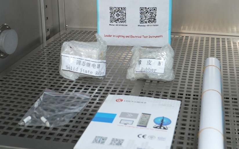
Figura 2
Download links for the digital user manual, warranty card, and other documents have been sent via email. Please download them as soon as possible. If you missed the email, please feel free to contact us to request the download links again.
1.3 Descrierea structurii echipamentului
1.3.1 Front View of the Test Chamber
① Control panel; ② Test chamber door (single or double, depending on the size of the test chamber); ③ Condenser ventilation openings.
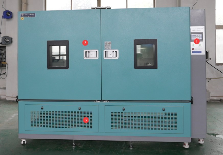
Figura 3
1.3.2 Vederi din spate și laterale ale camerei de testare
① Power cord; ② Refrigerant pressure gauge; ③ This is the overflow outlet; a small amount of water will flow out during the test. Simply connect this water pipe to a drain. A water pipe with an inner diameter of 10 mm is required.
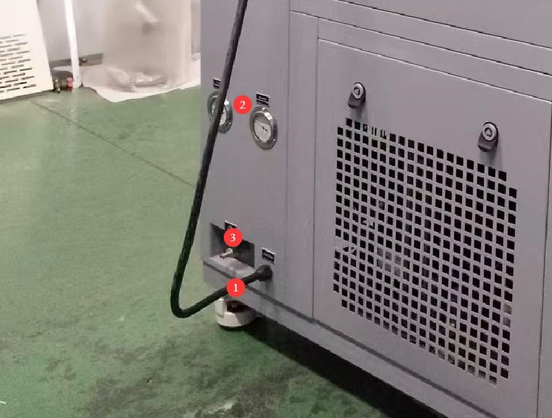
Figura 4
2. Măsuri de siguranță
2.1 Siguranța electrică
2.1.1 Conexiune la alimentare
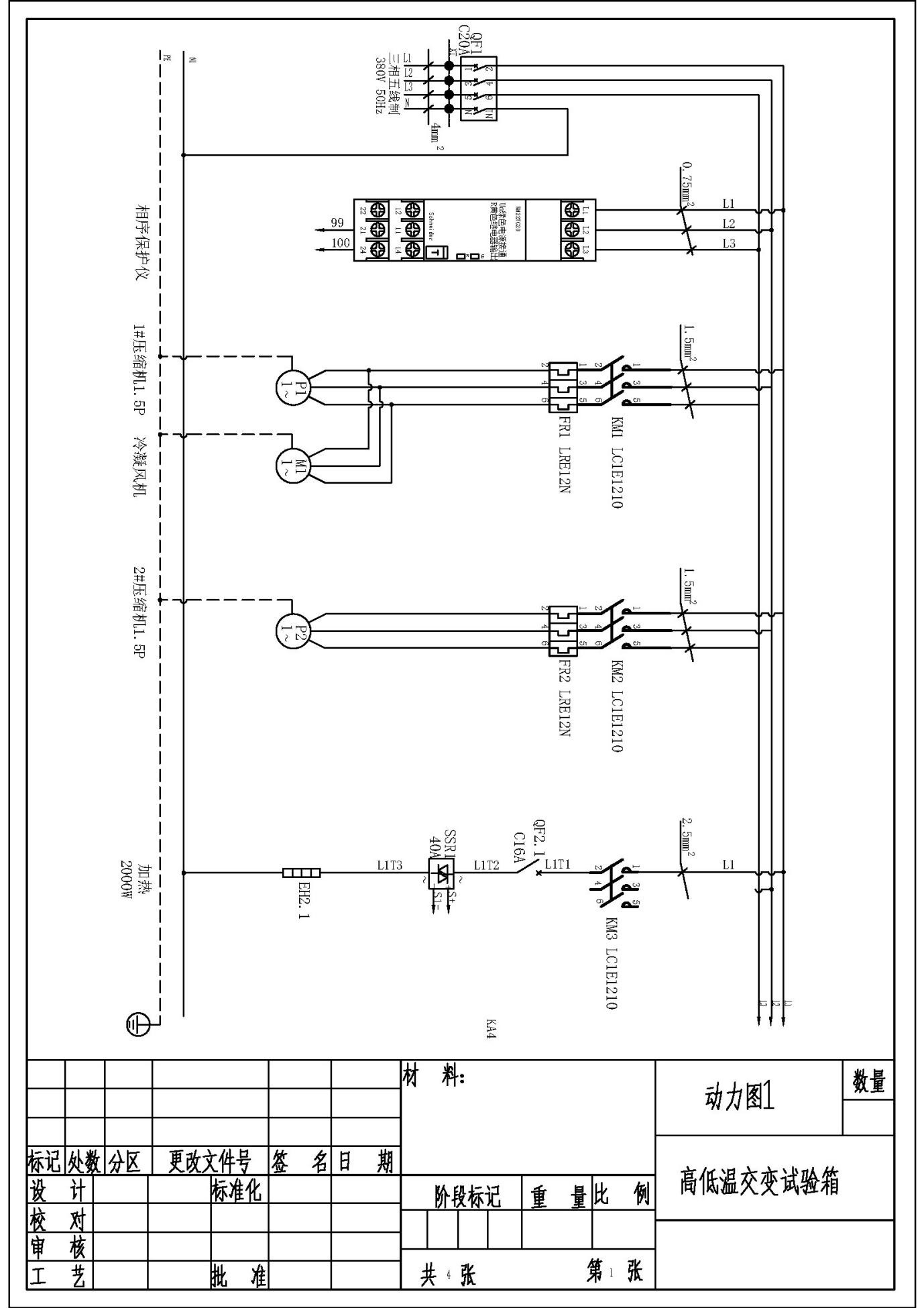
The equipment must be powered by a dedicated circuit with specifications of AC 380 V, 50 Hz (or 60 Hz, optional), three-phase, five-wire system. Multiple units must not share a single power source to prevent voltage drops that could cause abnormal equipment performance or unplanned downtime. Before connecting the power supply, ensure the power is turned off. When wiring, strictly distinguish between the live wires (L1, L2, L3), neutral wire (N), and ground wire (PE). The wiring sequence must comply with the requirements of the equipment’s electrical schematic; reversing the live and neutral wires is strictly prohibited.
The equipment is equipped with a phase sequence protector. After wiring, check the phase sequence before powering on: If the green “Un” light and the yellow “R” light on the phase sequence protector are both lit, the wiring is correct; If only one of the lights is on, or none are on, this indicates reverse phase. Turn off the main power supply, swap the positions of the two adjacent live wires (L1 and L2), and then check again;
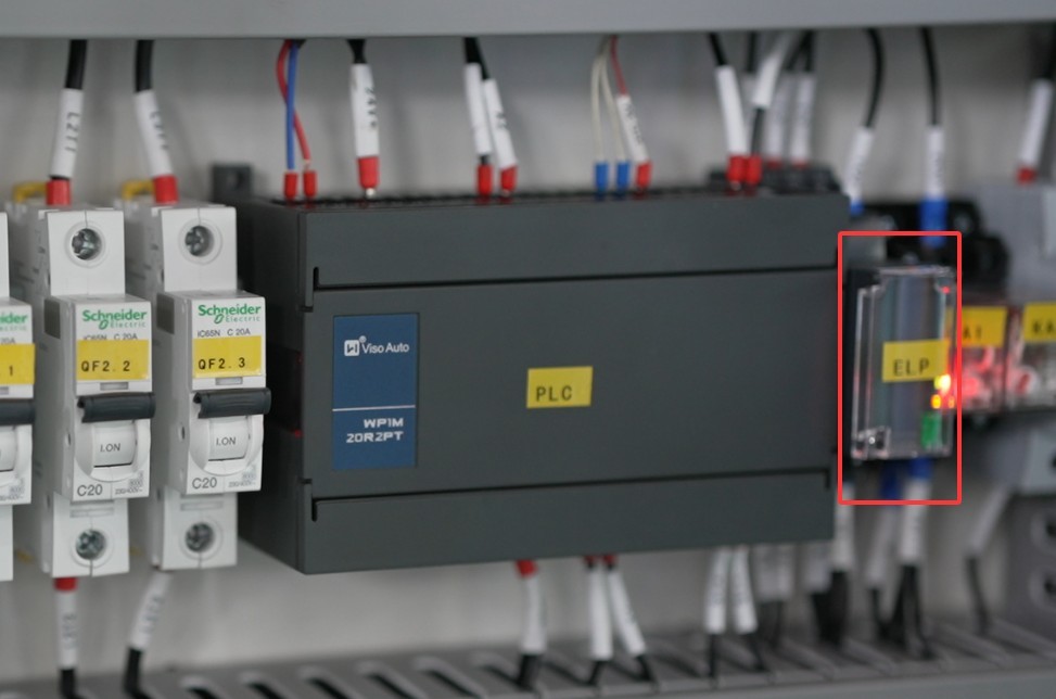
Figura 5
După finalizarea cablajului, trageți ferm de terminal pentru a vă asigura că conexiunea este sigură și că nu există slăbiri.
2.1.2 Specificații de împământare
The equipment must be reliably grounded, with a grounding resistance of ≤50 Ω. Do not use gas lines, non-metallic water pipes, or neutral wires as substitutes for the grounding wire. After grounding is complete, use a Grounding Resistance Tester to measure the grounding resistance. Power may only be applied after confirming that the requirements are met, to prevent electric shock, equipment malfunction, or measurement errors caused by poor grounding.
2.1.3 Contraindicații pentru procedură
Before wiring, inspecting, or maintaining the equipment, you must turn off the circuit breaker on the back of the equipment and disconnect the main power supply. Confirm that there is no residual voltage before proceeding;
Nu acționați comutatorul de alimentare, ecranul tactil sau butoanele instrumentului cu mâinile ude pentru a evita riscul de electrocutare;
Nu așezați obiecte străine (cum ar fi unelte sau hârtie) în interiorul tabloului de comandă electric pentru a preveni ca praful sau obiectele străine să provoace scurtcircuite sau să deterioreze componentele;
Nu conectați și nu deconectați cablurile de alimentare sau cablurile de semnal în timp ce echipamentul funcționează pentru a preveni scurtcircuitele care ar putea deteriora controlerul sau componentele electrice.
2.2 Siguranța operațională
2.2.1 Cerințe privind specimenele de testare
The equipment must not be used for testing flammable, explosive, toxic, or highly corrosive substances (such as alcohol, gasoline, strong acids, strong alkalis, etc.). Since the equipment is not equipped with explosion-proof devices, such substances may cause fires, explosions, or corrosion of the equipment;
If the test specimen generates heat (such as during power-on testing of electronic components), an external, independent power source must be provided for the specimen. Do not use the device’s own power supply directly to avoid overloading the device’s circuitry;
The sample volume must not exceed 80% of the test chamber’s capacity, and the weight must not exceed the specified load capacity of the shelves (30 kilograms per shelf) to prevent deformation of the shelves or disruption of the temperature cycling process.
2.2.2 Siguranța operațională
While the equipment is in operation, non-professionals are prohibited from disassembling or repairing it. In the event of a malfunction, contact after-sales service personnel or operate the equipment only under the guidance of a technician;
Avoid opening the chamber door as much as possible during the test. Opening the door when the temperature is extremely high or low may cause the operator to suffer burns or frostbite, and may disrupt the temperature equilibrium inside the chamber, thereby affecting the test results. If it is necessary to open the door, wear heat-resistant gloves and safety goggles, open the door slowly, and wait until the temperature inside the chamber has stabilized before proceeding;
Nu setați temperatura peste intervalul specificat pentru echipament; depășirea limitei de temperatură poate provoca arderea elementului de încălzire sau chiar un incendiu;
If the equipment triggers an alarm (the touchscreen automatically switches to the alarm code screen), immediately stop the test and troubleshoot the issue (see “Chapter 7: Troubleshooting and Resolving Common Issues”). Do not force the equipment to restart; operating the equipment before the fault is resolved may cause further damage.
2.2.3 Conduită interzisă
Do not open the control cabinet door while the equipment is running to avoid touching internal high-voltage components and causing an electric shock;
Do not disassemble core components such as the temperature sensor (PT100 platinum resistance thermometer) or heating elements without authorization. Modifying the equipment will void the warranty and may cause safety incidents;
Do not place heavy objects (such as tools, accessories, etc.) on top of the device to avoid damaging the device panel or impeding heat dissipation;
Nu așezați obiecte inflamabile (cum ar fi cutii de carton, folie de plastic etc.) în jurul echipamentului. Mențineți deschiderile de ventilație ale echipamentului libere pentru a preveni riscul de incendiu.
2.3 Siguranța mediului
2.3.1 Cerințe de instalare
Echipamentul trebuie instalat într-o încăpere climatizată, unde temperatura ambiantă este menținută între 5°C și 25°C, iar umiditatea relativă este ≤85%. Dacă umiditatea ambiantă este ridicată, se poate forma condens în apropierea ușii echipamentului și a orificiilor de testare; în astfel de cazuri, îmbunătățiți ventilația încăperii sau utilizați un dezumidificator;
The installation site must be free of high concentrations of dust, corrosive gases (such as sulfur dioxide and chlorine), and flammable or explosive atmospheres. Direct sunlight on the equipment is prohibited to prevent corrosion of the equipment housing and aging of electrical components;
Keep the device away from areas with significant fluctuations in ambient temperature, such as near vents and doorways, to prevent these fluctuations from affecting the device’s temperature control accuracy.
2.3.2 Cerințe de spațiu
The distance between the equipment enclosure and the wall, as well as surrounding fixtures (such as other test equipment and shelving), must be at least 1500 mm to ensure unobstructed ventilation at the equipment’s cooling vents (rear and sides);
At least 2000 mm of space must be left at the equipment door opening to ensure the door can be opened in any direction, facilitating the placement and removal of samples;
2.3.3 Plasare orizontală
Echipamentul trebuie așezat pe o suprafață plană. Folosiți o nivelă cu bulă de aer pentru a vă asigura că echipamentul este la nivel: Așezați nivela cu bulă de aer pe suprafața superioară a echipamentului și asigurați-vă că bula este centrată. Notă: Înălțimea următoarelor tipuri de picioare trebuie ajustată pentru a asigura că camera de testare este la nivel:
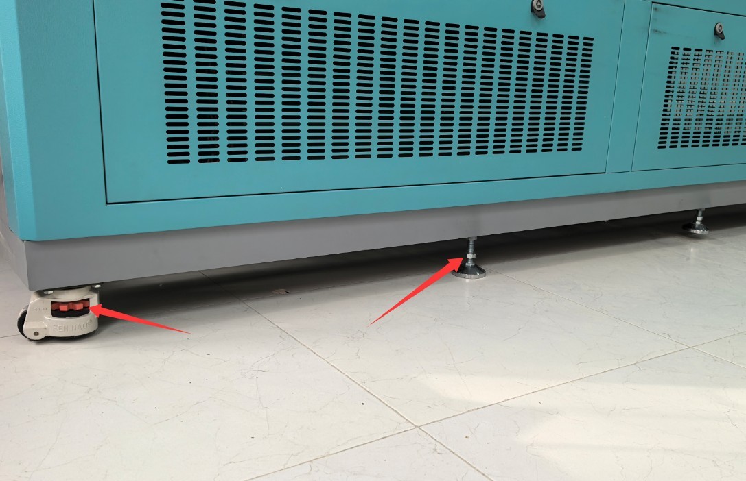
Figura 5.1
Dacă echipamentul este înclinat, acest lucru poate compromite stabilitatea structurală a camerei de testare, poate cauza o distribuție neuniformă a temperaturii în interiorul camerei sau chiar o etanșare deficitară a ușii, afectând astfel rezultatele testelor și durata de viață a echipamentului.
2.4 Altele
Pentru aspectele care nu sunt acoperite de acest manual, vă rugăm să procedați cu prudență sau să ne contactați.
3. Pregătiri înainte de test
3.1 Conectarea cablului de alimentare
Vezi 2.1.1.
3.2 Plasarea probei
Pentru restricțiile privind eșantionul, consultați secțiunea 2.2.1.
Note: If the sample requires the use of a cable, please reseal the side opening on the outside of the test chamber with a rubber plug, as shown in the figure below:
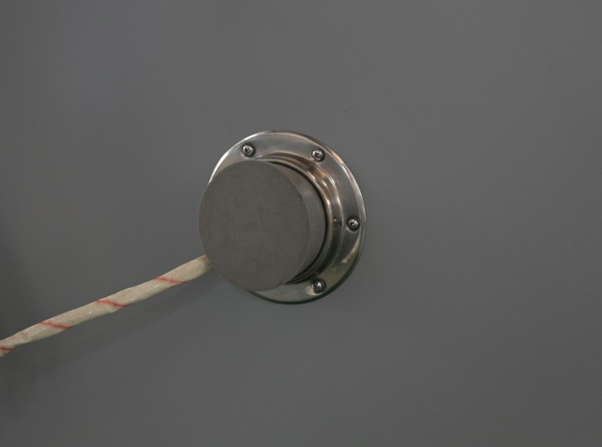
Figura 6
Samples must not come into contact with the inner walls of the test chamber; temperature probes must not be touched or covered; and airflow channels must not be obstructed. Samples must be securely fastened and must not move during the test.
3.3 Închiderea ușii dulapului
Make sure the box door is closed and the latch is securely locked. If it is a double door, press and lock the left door first, then press and lock the right door.
3.4 Punerea în funcțiune a camerei de testare
3.4.1 Turn on the power to the test chamber
Press the “Power” button on the control panel on the front of the device. The touchscreen program will enter standby mode. Ensure that there are no alarms in the program; if there are any alarms, refer to Chapter 7 for troubleshooting.
4. Program Operation via the Touchscreen of The High And Low Temperature Chamber
4.1 Introducere în ecranul principal
Sistemul intră automat în ecranul de monitorizare la pornire. Faceți clic pe „PRINCIPAL” în colțul din dreapta sus pentru a accesa ecranul principal.
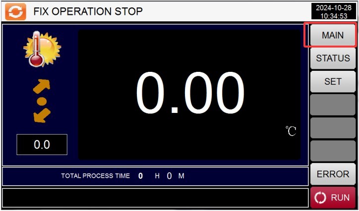
Figura 7
From left to right and top to bottom, they are: ① Curve display; ② Monitoring screen; ③ Operation settings; ④ Program group settings; ⑤ Scheduled settings; ⑥ Display settings.
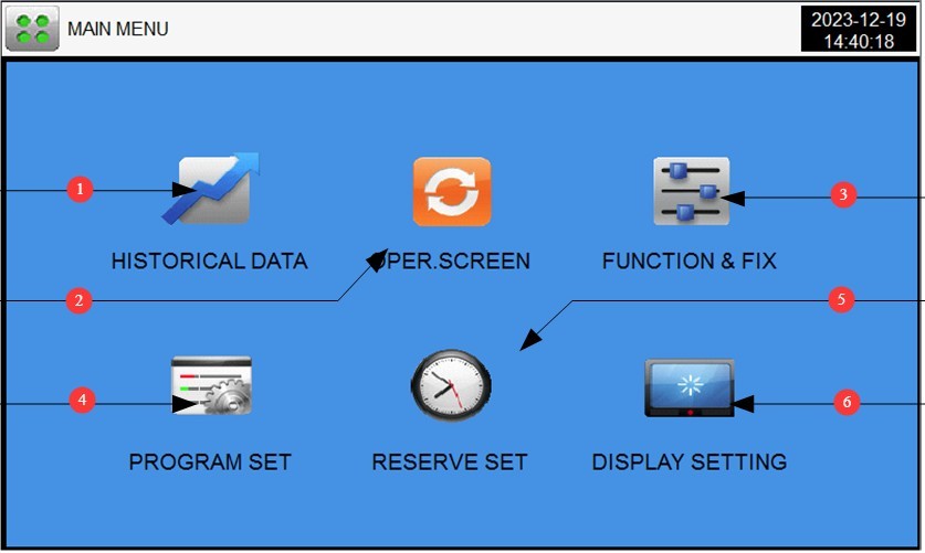
Figura 8
4.2 Setări de operare
Go to the “Operation Settings” screen. ① Select the test operation mode: FIX (fixed value) or PRO (program); ② Set the test completion action: no action or return to ambient temperature. If you want the system to automatically return to ambient temperature, set the ambient temperature range.
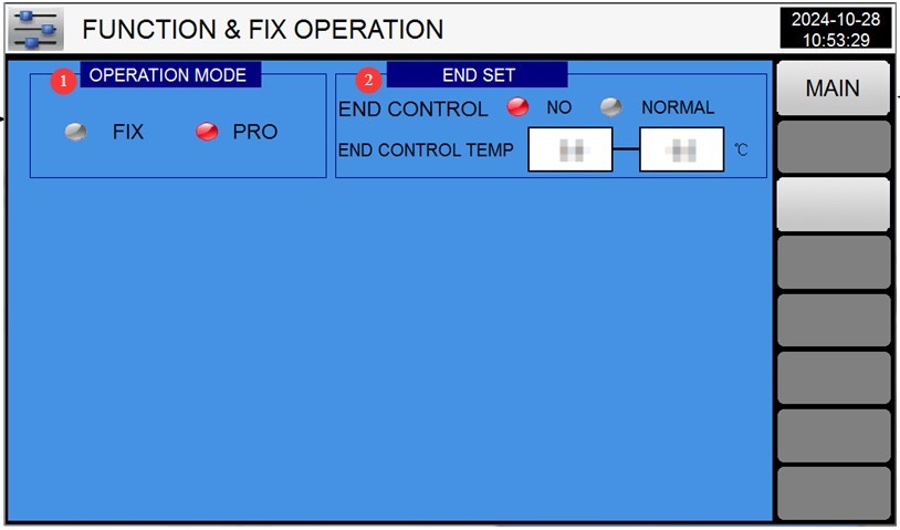
Figura 9
4.3 Setări programări
Go to the “Scheduled Settings” screen. ① The left column displays the current time; ② in the right column, enter the scheduled time. Then press the “RESERVE” button on the far right until it turns red—this confirms the schedule has been set, and the test chamber will automatically begin the test at the scheduled time.
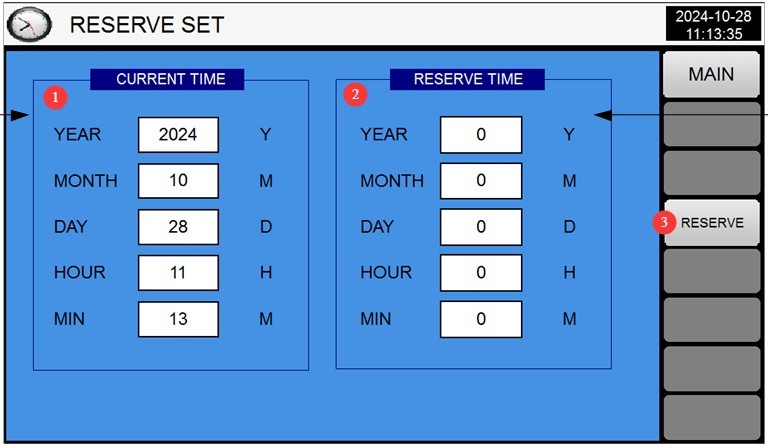
Figura 10
4.4 Setări de afișare
Go to the “Display Settings” screen. ① Select the display language; ② Power-off recovery mode (Stop: After a power failure during operation, the system returns to the “Stop” state when power is restored; Cold Start: After a power failure during operation, the system restarts from the first segment when power is restored; Hot Start: After a power outage interrupts operation, the system continues from the segment where operation was interrupted before the outage, restoring the system to its pre-outage state when power is restored).
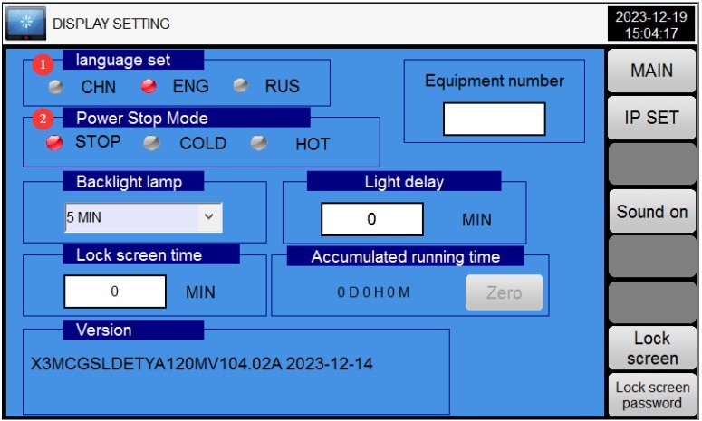
Figura 11
4.5 Funcționare cu valoare fixă (test la un singur punct de temperatură și umiditate)
4.5.1 Accesarea setărilor cu valoare fixă
Selectați „Valoare fixă” în „Setări de funcționare”. Accesați „Ecran de monitorizare”, apoi faceți clic pe butonul „Setări” din dreapta pentru a deschide ecranul „Setări valoare fixă”.
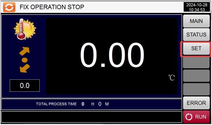
Figura 12
4.5.2 Setări parametri
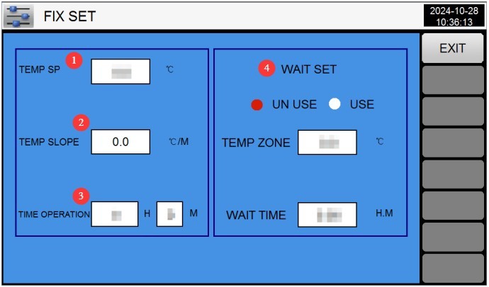
Figura 13
① Setarea temperaturii: Introduceți temperatura țintă (consultați Secțiunea 1.1 pentru intervalul de temperatură configurabil).
② Temperature ramp rate: Unless a specific ramp rate has been customized, use the default value of 0. The test chamber will operate using the automatic ramp rate.
③ Funcționare temporizată: Introduceți durata testului (de exemplu, 2 ore; interval: 0–9999 ore); când este setată la 0, testul trebuie oprit manual.
④ Wait Setting: If the wait function is selected, the test time will not begin until the test chamber reaches the set temperature. You must also set the wait tolerance (the test is considered complete if the temperature falls within this tolerance range) and the wait time (if the test chamber has not reached the set temperature by the end of the wait time, the test time will automatically begin).
4.5.3 Pornirea testului de calibrare
After verifying that the parameters are correct, return to the monitoring screen and click the “Run” button in the lower-right corner.
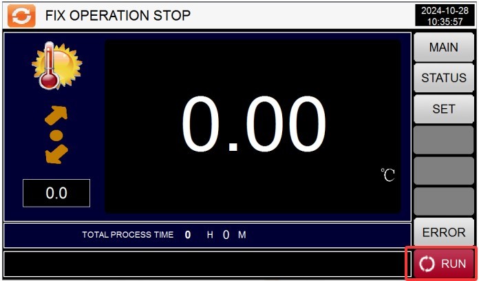
Figura 14
4.6 Funcționarea programului (test de temperatură în mai multe etape)
4.6.1 Ecranul Setări Grup de Programe
① Număr program: Puteți seta până la 100 de programe, numerotate de la 1 la 100, asigurându-vă că numerele nu se suprapun cu programele existente; ② Introduceți numele programului; ③ Editați programul; ④ Setați bucla; ⑤ Setați timpul de așteptare.
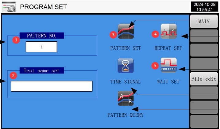
Figura 15
4.6.2 Accesarea ecranului de editare a programului
① Test segment number; each program can have up to 99 test segments; ② Temperature setting; ③ Test duration setting;④ The relay is set to automatic operation; no changes are needed to the parameters here; ⑤ Switch between segment numbers; ⑥ Insert or delete a segment; ⑦ Number of segments to run in this program. For example, if you only want to run the first four segments of this program, enter 4. Please enter the correct number; otherwise, the program will not run properly; ⑧ Return to the program group settings screen.
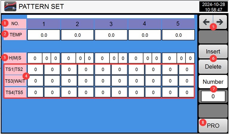
Figura 16
Exemplu: Dacă trebuie să efectuați următoarele teste: Pasul
1: Temperature -20°, test duration 3 hours;
Step 2: Temperature 150°, test duration 5 hours. The
setările ar trebui să fie:
| NU. | 01 | 02 | 03 | 04 | 05 ... |
| Temperatura | -20 ° | Pentru suprafețe de până la | 0 | ||
| Timp | 0.01.00 | 3.00.00 | 0.01.00 | 5.00.00 | |
NR. 01: Faza de tranziție — timpul necesar pentru atingerea temperaturii țintă.
NR. 02: Durata efectivă a testului: 3 ore.
NR. 03: Faza de tranziție — timpul necesar pentru atingerea temperaturii țintă.
NR. 04: Durata reală a testului — 5 ore.
Note 1: For each identical temperature and humidity setting, two phases must be configured: the first is the transition phase—the time required for the test chamber to reach the set temperature—and the second is the test duration at that temperature.
Note 2: In the examples above, the transition phase was set to only 1 minute. The equipment has a wait function; even if the set time is short, the equipment will reach the set value before proceeding to the next phase. This setting minimizes the equipment’s preparation time, thereby saving test time.
4.6.3 Ecranul Setări Buclă
① Number of loops for the current program; the default value is 1, meaning the test stops immediately after the current program is completed; ② Linked program number; this specifies whether the test will automatically skip to another program to continue testing after the current program is completed. Enter 0 if this is not required; ③ Loop mode for the current program’s test segments; the default value is 0 for all segments, meaning the test does not repeat and proceeds sequentially from the first segment to the last.
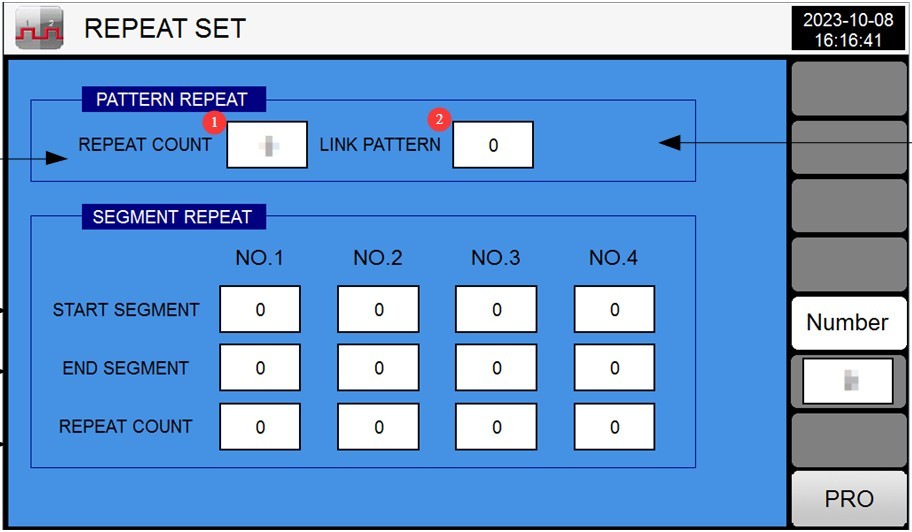
Figura 17
Example: The figure below means: After the current program has been run twice, it will automatically proceed to Test Program 3 to continue testing.
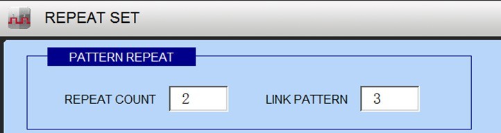
Figura 18
The diagram below illustrates that the current test sequence for the program is 01>02>03>04>05>03>04>05>02>03>04>02>03>04>05>06>07…
ceea ce înseamnă că testarea începe cu primul segment. Secțiunile 3-5 sunt repetate de două ori, urmate de secțiunile 2-4 care sunt repetate de două ori, iar apoi secțiunile de testare rămase sunt completate în secvență.
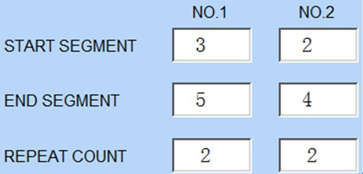
Figura 19
Pe baza logicii de mai sus, puteți configura parametrii de testare ai programului pentru a îndeplini propriile cerințe de testare.
4.6.4 Așteptați ecranul Setări
① Selectați „TOATE” pentru a activa funcția de așteptare pentru toate segmentele de testare; ② Valoarea erorii zonei de așteptare; ③ Timp maxim de așteptare.
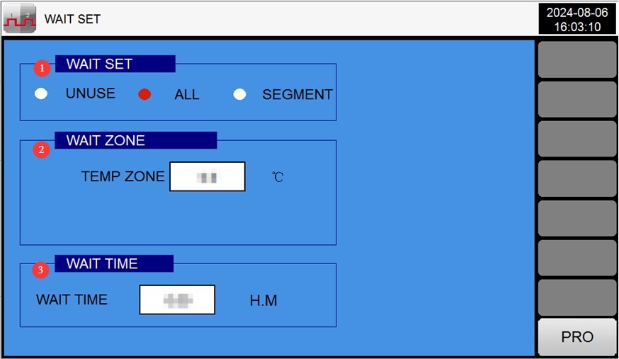
Figura 20
4.6.5 Boot Sequence Test
After verifying that the parameters are correct, return to the monitoring screen and click the “Run” button in the lower-right corner.
4.7 Testarea funcționării și monitorizarea
4.7.1 Ecran de monitorizare
Ecranul monitorului afișează temperatura setată și temperatura reală curentă.
4.7.2 Real-Time Fault Monitoring
If a fault occurs, the touchscreen automatically switches to the “Real-Time Fault Display Screen.”
Check the error codes and refer to Chapter 7 for troubleshooting and resolution; click “Mute” to turn off the buzzer, and click “Reset Errors” once the issue has been resolved.
4.7.3 Vizualizarea și exportarea curbelor
Atingeți ecranul „Afișaj curbă” de pe ecranul principal pentru a vizualiza curba temperaturii în timp real.
Introduceți unitatea USB, faceți clic pe „Descărcare”, iar datele curbei vor fi salvate pe unitatea USB în format CSV (care poate fi deschis și analizat pe un computer).
Tap “Clear History” (press and hold for 5 seconds) to delete old curve data (proceed with caution).
5. Proceduri post-test
5.1 Proceduri de oprire a echipamentului
5.1.1 Încheierea programului
Dacă programul se termină normal: Dispozitivul funcționează conform „Modului de terminare a programului” (de exemplu, „Revenire la temperatura ambiantă”, răcindu-se automat până la intervalul setat de temperatură ambiantă).
To stop the process midway: Click the “Stop” button on the monitoring screen, and the device will enter standby mode.
5.1.2 Proceduri de oprire
Verify that the device is in standby mode (not running), then turn off the power switch on the device’s control panel.
Opriți întrerupătorul principal.
5.2 Sample Removal and Handling
Wear gloves rated for high and low temperatures (even if the sample has “returned to room temperature,” it may still retain residual heat), open the chamber door, and slowly remove the sample.
Se inspectează starea probelor (de exemplu, aspectul, performanța) și se înregistrează datele de testare (temperatura, umiditatea, timpul, modificările probelor).
If there is any liquid residue on the sample, wipe it clean with a lint-free cloth to prevent contamination of the work area.
5.3 Curățarea echipamentelor
Cleaning the Inner Chamber: Wipe the inner walls and shelves of the chamber with a lint-free cloth dampened with alcohol to remove any residual sample stains (do not spray water or alcohol directly onto the surfaces).
Curățarea ușii frigiderului: Ștergeți garnitura ușii (pentru a îndepărta praful) și verificați dacă garnitura nu este deformată (dacă există pete, ștergeți-le cu o cârpă umedă).
Cleaning the Outer Case: Wipe the equipment casing with a dry cloth to remove surface dust (do not use gasoline or organic solvents, to prevent the paint from peeling).
Curățarea ecranului tactil: Ștergeți cu o lavetă uscată pentru a îndepărta amprentele și a asigura sensibilitatea tactilă.
5.4 Test Records
Fill out the equipment usage log, recording the following information: test date, program group, sample name, runtime, any malfunctions (if applicable), and operator.
Organizați datele de testare (cum ar fi grafice și rapoarte eșantion) și arhivați-le pentru a le păstra în siguranță.
6. Întreținerea și îngrijirea zilnică a echipamentelor
6.1 Curățare și întreținere regulată
6.1.1 Curățare de rutină (după fiecare test)
| Proiecte de întreținere | Proceduri de întreținere | Note importante |
| Chamber Liner | Wipe with an alcohol-soaked lint-free cloth to remove stains | Nu spălați cu apă; evitați expunerea componentelor electrice la umezeală. |
| Bandă de etanșare | Wipe with a dry cloth and check for any deformation or damage. | Dacă garnitura de cauciuc este uzată (și nu mai etanșează corect), contactați serviciul clienți pentru a o înlocui. |
| Touchscreen | Ștergeți cu o cârpă uscată pentru a îndepărta amprentele și praful | Nu zgâriați ecranul cu obiecte ascuțite. |
| Deschidere de ventilație | Wipe off surface dust with a dry cloth and ensure proper ventilation. | Do not block the ventilation openings (to prevent overheating) |
6.1.2 Curățare regulată
| Proiecte de întreținere | Ciclul de întreținere | Instrucțiuni de întreținere | Obiective și cerințe |
| Senzor De Temperatura | Lunar | Folosiți o perie cu peri moi pentru a îndepărta praful de pe suprafața senzorului | Precizie de măsurare în limita a ±2°C/±3% RH |
| Rezistența la sol | La fiecare 3 luni | Inspecția testerului de rezistență la împământare | Rezistență la împământare ≤ 50 Ω |
| Componente electrice | La fiecare 6 luni | Deschideți ușa tabloului de distribuție și verificați dacă releele și blocurile de conexiuni sunt fixate. | No oxidation or loose connections; the circuit breaker is functioning normally. |
6.2 Long-Term Deactivation for Maintenance (Deactivated for More Than 1 Month)
6.2.1 Dezactivarea preprocesării
După finalizarea tuturor testelor, opriți alimentarea și deconectați unitatea conform descrierii de la 5.1.2;
Curățați temeinic echipamentul (rezervorul interior, carcasa exterioară și tabloul electric);
Open the door of the unit and allow the inner chamber to air out and dry naturally (to prevent mold growth);
Remove all samples and shelves (if any) from the equipment and store them separately.
6.2.2 Întreținere în timpul perioadei de nefuncționare
Porniți unitatea cel puțin o dată pe lună (timp de 30 de minute, pentru a permite ventilatorului de circulație și controlerului să funcționeze) pentru a preveni umezirea componentelor;
Inspectați exteriorul echipamentului pentru a preveni acumularea de praf; îl puteți acoperi cu o husă de praf (fabricată dintr-un material respirabil);
Inspect the storage environment to avoid humidity, high temperatures, or corrosive gases.
6.2.3 Verificări prealabile reactivării
Remove the dust cover and clean the equipment;
Check that the power lines and grounding are in good working order;
După pornirea alimentării, verificați dacă regulatorul, ventilatorul și sistemul de încălzire funcționează normal;
Conduct one short-term fixed-condition test (e.g., 50°C for 30 minutes) to verify that the equipment is functioning properly before proceeding with the formal test.
7. Depanarea și rezolvarea problemelor comune
7.1 Alarme cu ecran tactil
| Codurile de depanare | Cauze posibile | Soluţie |
| PT1: Temperature Sensor Malfunction | Sonda PT100 este defectă; rezistența sa la temperatura camerei este de 110 Ω; un punct de pe modulul PLC este defect; Cablajul PT100 este slăbit. |
Înlocuiți sonda PT100; reparați sau înlocuiți modulul PLC; rewire |
| X2 Temperature Control Over-Temperature Protection | Corrosion at the connection points or exposure to water; uncontrolled încălzire, rezultând o creștere anormală a temperaturii; motor is not running, preventing heat from escaping from inside the heating element; the impeller has fallen off, preventing heat from escaping from inside the heating element |
Clean or rewire; verificați ieșirea în stare solidă; Verificați dacă există tensiune de 220V între firele roșu și galben ale motorului; dacă nu există tensiune, înlocuiți motorul; dacă există tensiune, înlocuiți condensatorul; reinstall the impeller |
| Protecție la supraîncălzire a camerei de testare X3 | Valoarea de referință a protecției la supratemperatură este mai mică decât valoarea de referință a regulatorului | 1. Adjust the over-temperature protection setpoint to match that of the controller. |
7.2 Defecțiuni legate de controler
7.2.1 Controller Without a Digital Display
| Simptome de eroare | Cauze posibile | Soluţie |
| The controller screen is black; there is no display. | 1. The power plug is not properly connected; 2. The power outlet has no power, or there is a missing phase in the three-phase power supply; 3. The wiring at the controller’s power supply terminals has come loose; 4. Internal controller malfunction; 5. The control cabinet door is open, causing the power circuit breaker to trip. | 1. Plug the power cord in securely; 2. Check the power outlet and use a multimeter to verify that the three-phase power supply is normal; 3. Turn off the main power, open the electrical cabinet, check the wiring at the controller’s power supply terminals (e.g., 24 VAC), and retighten the connections; 4. Contact the manufacturer to repair or replace the controller;5. Close the control cabinet door, reset the circuit breaker (inside the control cabinet), and verify that it has closed. |
7.2.2 Controlerul afișează caractere denaturate sau numerele pâlpâie
| Simptome de eroare | Cauze posibile | Soluţie |
| The display shows garbled characters or is unstable | 1. Conexiune slăbită între controler și senzor; 2. Termometrul cu rezistență de platină (senzorul de temperatură) este deteriorat sau are o îmbinare de lipire defectuoasă; 3. Interferențe semnificative la sursa de alimentare (de exemplu, echipamente de mare putere în apropiere); 4. Defecțiune internă a controlerului | 1. Disconnect the main power supply, inspect the sensor terminals, and retighten them; 2. Replace the platinum resistance sensor (model PT100, 3-wire system, wire resistance ≤ 10 Ω), and resolder it; 3. Eliminate power supply interference (e.g., keep the device away from high-power equipment and use a regulated power supply);4. Contact the manufacturer to repair or replace the controller |
7.3 Defecțiuni ale sistemului de încălzire
7.3.1 The unit is not heating or cooling
| Simptome de eroare | Cauze posibile | Soluţie |
| Fără încălzire | 1. Over-temperature protection activated (buzzer alarm); 2. Set temperature is lower than the current actual temperature; 3. Solid-state relay failure; 4. Heating element failure; 5. Platinum resistance open circuit (no signal from the sensor); 6. Heating circuit fuse blown | 1. Check the over-temperature protection setpoint, reset it (to 20°C higher than the test temperature), and press the [Fault Reset] button; 2. Reset the temperature (to a value higher than the current actual temperature);3. Disconnect the main power supply and use a multimeter to test the solid-state relay; replace it if damaged; 4. Measure the resistance of the heating element (normally several tens of ohms); replace it if damaged; 5. Inspect the platinum resistance wire connections and replace any open-circuit platinum resistors; 6. Replace the heating circuit fuse (4 A). |
| Nu se răcește | 1. Comutatorul de răcire nu este pornit; 2. Compresorul nu a pornit; 3. Există o scurgere de agent frigorific | 1. Go to “Operation Settings” and turn on the cooling switch; 2. Check the compressor power supply and phase sequence, then wait 3–5 minutes before restarting; 3. Contact customer service to locate the leak and recharge the refrigerant. |
| Răcire lentă | 1. Insufficient refrigerant; 2. Clogged condenser; 3. Excess moisture in the chamber | 1. Completați cu agent frigorific (până la cantitatea specificată pentru echipament); 2. Curățați praful din condensator; 3. Uscați umezeala din cameră înainte de a reduce temperatura. |
7.3.2 Încălzire necontrolată (creștere continuă a temperaturii)
| Simptome de eroare | Cauze posibile | Soluţie |
| The temperature exceeds the set value and continues to rise | 1. The temperature setpoint is too high (exceeds the equipment’s upper limit); 2. The solid-state relay is stuck (cannot open); 3. The platinum resistance sensor is shorted (abnormal sensor signal); 4. Controller malfunction (cannot output a stop signal) | 1. Immediately turn off the main power supply and reset the temperature; 2. Replace the solid-state relay; 3. Inspect the platinum resistance thermometers and replace any that are shorted; 4. Contact the manufacturer to repair or replace the controller |
7.4 Condiții anormale de funcționare și defecțiuni
7.4.1 The Circulation Fan Is Not Running
| Simptome de eroare | Cauze posibile | Soluţie |
| Ventilatorul nu se rotește și este silențios. | 1. The fan’s power supply wiring has come loose; 2. The fan’s overcurrent protection has tripped (thermal relay tripped); 3. The fan motor is damaged; 4. The controller is not sending a signal to start the fan | 1. Turn off the main power supply, check the fan’s terminal connections, and retighten them; 2. Reset the thermal relay (inside the electrical cabinet) and check whether the fan is jammed; 3. Test the fan motor’s resistance (which should normally be several tens of ohms); if it is damaged, replace it; 4. Check the fan control parameters on the controller and contact the manufacturer for troubleshooting. |
7.4.2 Poor Cabinet Door Seal (Temperature Leakage)
| Simptome de eroare | Cauze posibile | Soluţie |
| Fluctuații semnificative de temperatură în timpul funcționării; încălzire lentă | 1. The door gasket is worn or damaged; 2. The door hinges are loose, causing the door to be crooked; 3. The door latch is loose and does not close securely | 1. Replace aged or damaged weatherstripping; 2. Adjust the cabinet door hinges and tighten the screws to ensure the door is plumb; 3. Adjust the position of the latch to ensure the weatherstripping is pressed tightly against the door when it is closed. |
7.5 Eroare de comunicare (PLC fără răspuns)
7.5.1 Întrerupere a comunicării (Ecranul afișează „PLC fără răspuns”)
| Simptome de eroare | Cauze posibile | Soluţie |
| Communication between the touchscreen and the PLC has been interrupted; control is not possible. | 1. The communication cable (RS-485) is loose or disconnected; 2. The communication cable is damaged (e.g., broken or shorted); 3. PLC power failure; 4. Mismatched communication parameters (e.g., baud rate, address) | 1. Disconnect the main power supply, inspect the RS-485 communication cable terminals, and retighten them; 2. Replace the damaged communication cable (use shielded cable to reduce interference); 3. Check the PLC power supply (e.g., 24V) to ensure it is functioning properly;4. Check the communication parameters (baud rate, address) between the controller and the PLC to ensure they match, and contact the manufacturer for guidance on adjustments |
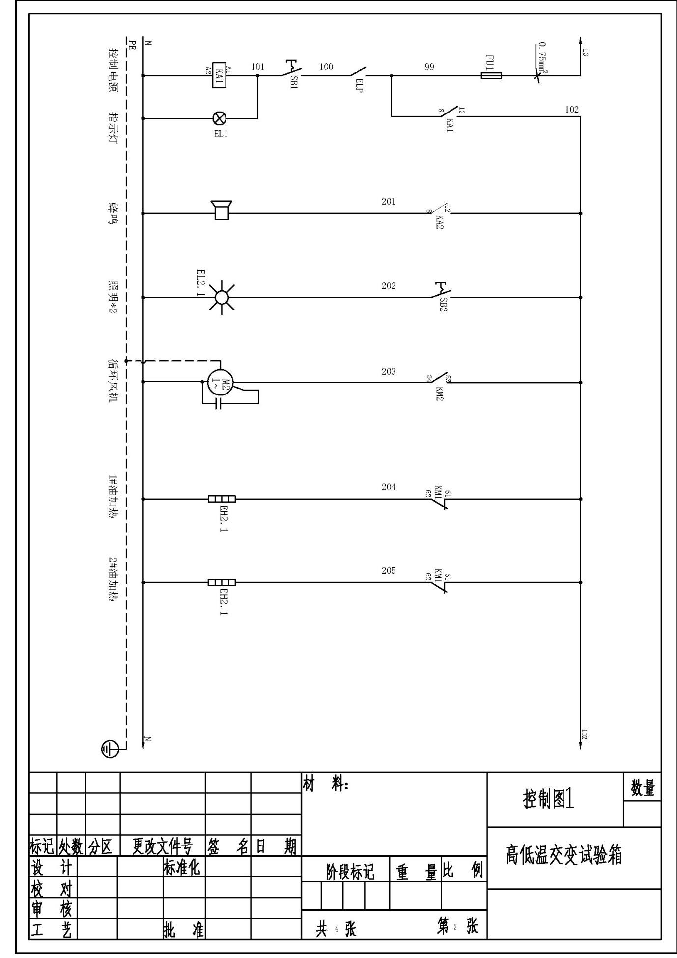
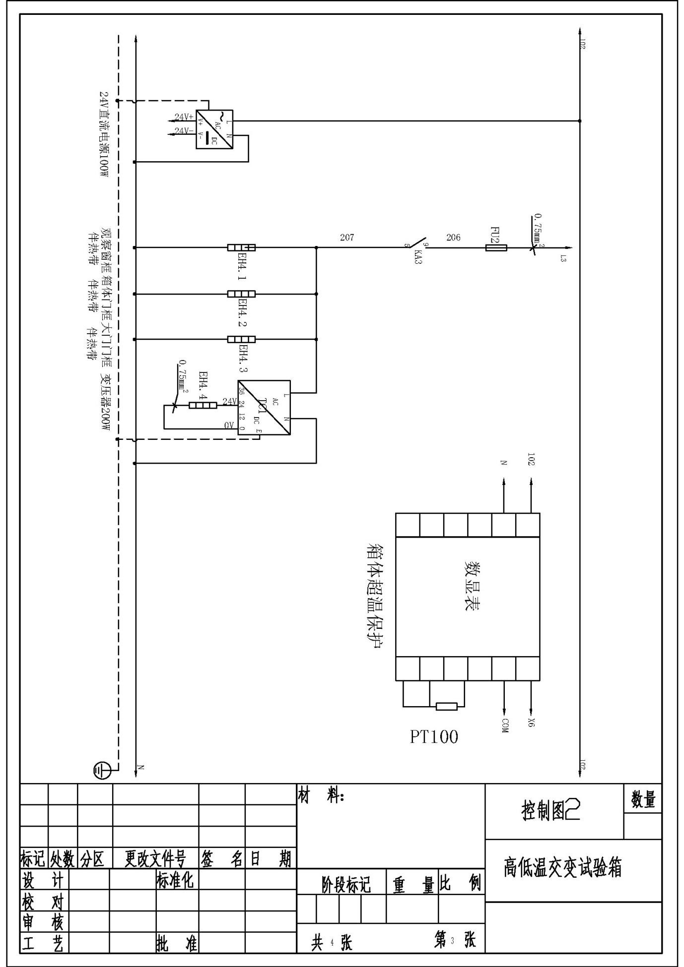
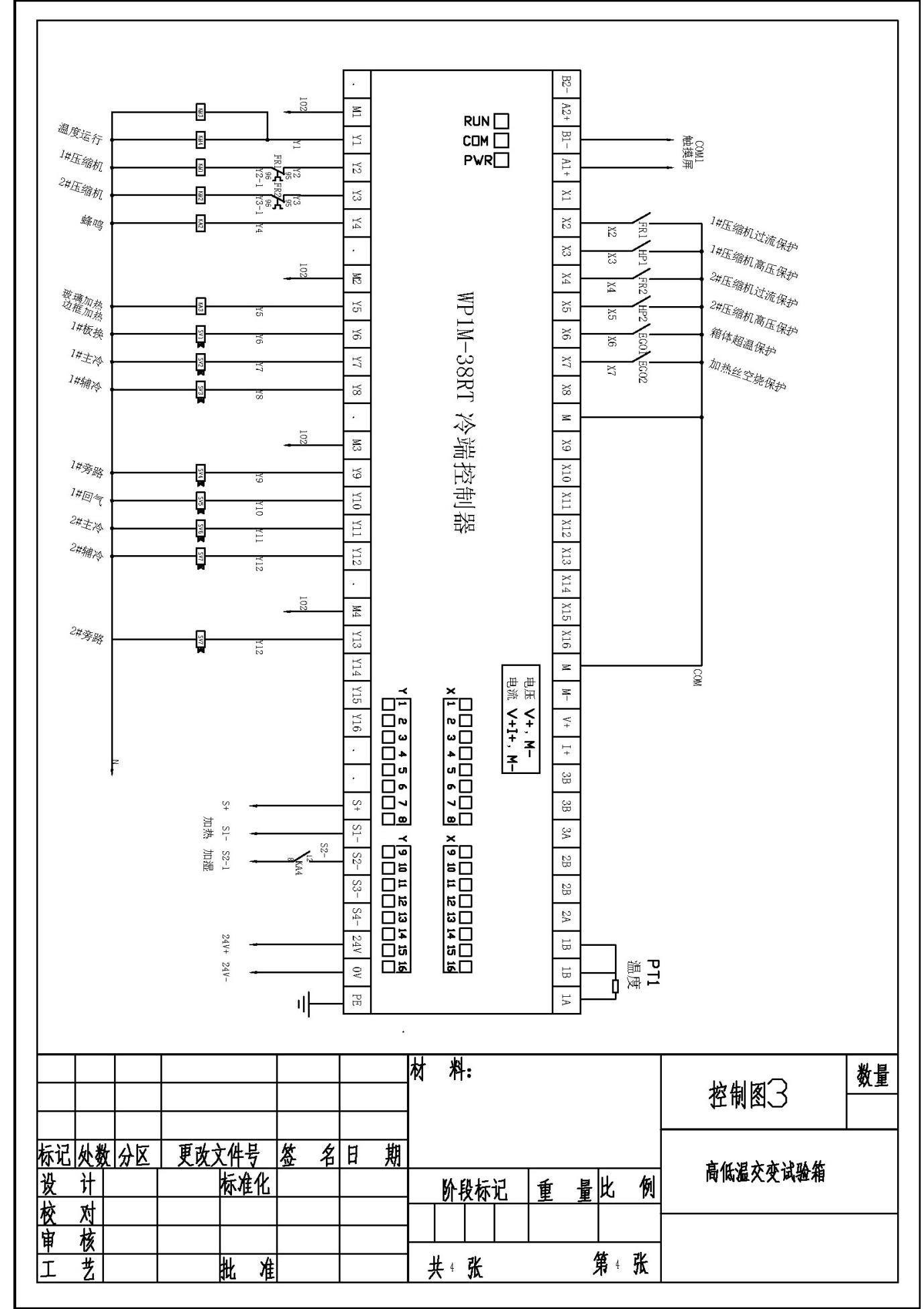
Appendix: Electrical Schematics