
 Engleză
 中文简体
中文简体 Русский
 Español
 Português
 Türkçe
 العربية
 Deutsch
 Polski
 Italiano
 Français
 한국어
한국어 ไทย
ไทย Tiếng Việt
 日本語
日本語





























Placă frontală fictivă pentru creșterea temperaturii
Manual de utilizare
Aplicabil LISUN models: GNGPL-3617
1. Noțiuni de bază despre echipament
1.1 Domeniul de aplicare
This device is suitable for conducting temperature rise type tests on 13A fuse-type plugs—both re-connectable and non-re-connectable—that comply with the BS 1363-1 standard. It verifies that the plug and its surrounding connections do not reach excessive temperatures under normal operating conditions, thereby ensuring product safety.
1.2 Standarde aplicabile
1.2.1 Standarde aplicabile
BS 1363-1:2023, Chapter 17: Temperature Rise; BS 4662:2006+A1:2009: Specification for Flush-Mounted Junction Boxes; BS 4800:2011: Specification for the Color of Architectural Paints(Color No. 08 C 35); BS EN 50525-2-11:2011 Specification for flexible cables with polyvinyl chloride (PVC) insulation; BS 6004:2012 Specification for power and control cables.
1.2.2 Diagrams Corresponding to the Standard
Figure 17a: Test apparatus for temperature rise test (temperature rise test cabinet).
Figure 17b: Dummy front plate for temperature rise simulation.
1.3 Principiul de funcționare
1.3.1 Test Principles
The temperature rise test simulates the heat generation of a plug during normal operation by applying a specified test current to the plug under test. Within a test chamber compliant with the standard, a fine-wire thermocouple is used to measure temperature changes at key locations on the plug. The temperature rise relative to an ambient reference point is calculated and compared with the standard limits to determine whether the product meets the requirements.
1.3.2 Principles of Thermal Equilibrium
The test continues with power applied until the system reaches thermal equilibrium, as determined by a temperature change of no more than 1 K within 1 hour; the temperature rise recorded at that point is the final test result.
1.4 Descărcarea documentelor electronice
We have already sent the download links for the electronic user manual, calibration certificate, warranty card, and other documents via email at the time of shipment. Please download them promptly. If you have not received the email, please contact us to obtain the download links again.
2. Măsuri de siguranță
2.1 Siguranța mediului
2.1.1 Mediul de instalare
Tests should be conducted in a well-ventilated indoor environment without forced airflow; avoid direct sunlight on the test chamber to prevent fluctuations in ambient temperature from affecting test accuracy; the test area should be located away from sources of airflow disturbance, such as air conditioning vents, doors, and windows.
2.1.2 Fire Safety Requirements
The test area is equipped with dry-powder fire extinguishers to address the risk of electrical fires; if you smell a burning odor or notice smoke during the test, immediately cut off the power and stop the test; do not store flammable items inside the test cabinet.
2.2 Siguranța electrică
Although the output terminal carries low voltage and high current during testing, do not touch live conductors with your bare hands. Under no circumstances should you open the test cabinet door to adjust internal wiring while the equipment is energized.
Since test currents can reach tens of amperes, the terminals must be securely fastened to prevent localized overheating caused by poor contact; all connection points in the current circuit should be inspected regularly to avoid abnormal heating caused by oxidation or loosening.
2.3 Siguranța operațională
2.3.1 High-Temperature Protection
During testing, the temperature of the plug pins and terminals may reach 60°C or higher; do not touch them directly. After testing is complete, wait until the sample has cooled completely before removing it to prevent burns.
2.3.2 Siguranța mecanică
The test cabinet must be placed on a level surface, with the heat dissipation space specified in the standard left clear on all sides; when opening the switchgear door, take care to avoid scratching your hands on the edges of the plywood; when tightening terminals with a torque wrench, follow the specified torque values and do not exceed them.
3. Prezentare generală a echipamentului
3.1 Diagramă standard
3.1.1 Temperature Rise Test Cabinet
See Figure 3-1 (taken from BS 1363-1:2023, Figure 17a).
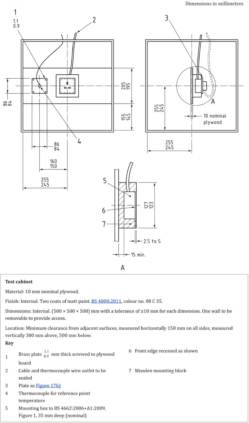
Figura 3-1
3.1.2 Front Panel Components for Temperature Rise Simulation
See Figure 3-2 (taken from BS 1363-1:2023, Figure 17b).
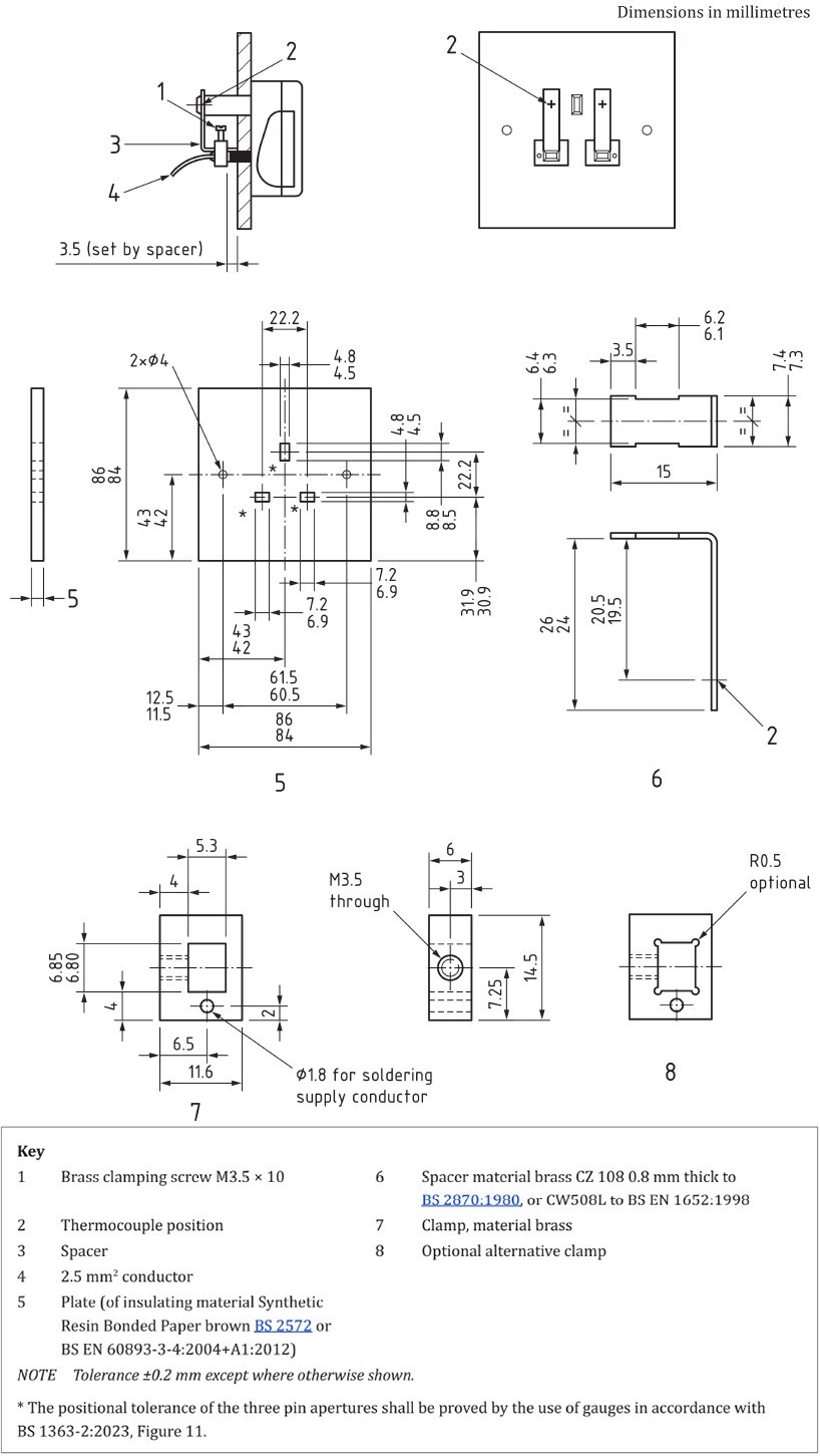
Figura 3-2
3.2 Fotografii ale obiectului real
3.2.1 Appearance of the Test Cabinet
Vezi Figura 3-3.
| Număr | notițe |
| ① | Ușa cabinetului |
| ② | Cable and Thermocouple Grommets |
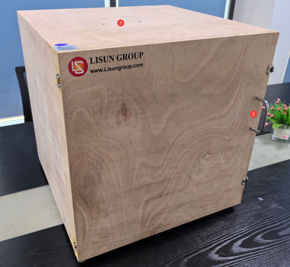
Figura 3-3
3.2.2 Interior of the Test Cabinet and Accessories
Vezi figurile 3–4.
| Număr | notițe |
| ① | Cable and Thermocouple Grommets |
| ② | Mounting plate, located in the center of the test cabinet |
| ③ | Brass plate, used for mounting a reference-temperature thermocouple. Corresponds to No. 1 in Figure 17a. |
| ④ | Wooden mounting block for installing flush-mount boxes and analog panels. Corresponds to No. 7 in Figure 17a. |
| ⑤ | Simulation panel, corresponding to No. 5 in Figure 17b |
| ⑥ | Brass clamping component, corresponding to item 8 in Figure 17b |
| ⑦ | Spacer, corresponding to No. 6 in Figure 17b |
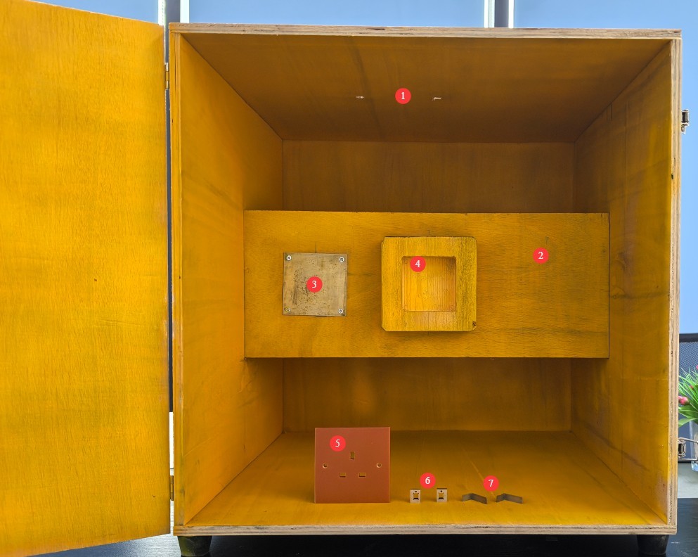
Figura 3-4
3.3 Echipamente de susținere
3.3.1 Required Supporting Equipment
LISUN WS Series Temperature Rise Tester features the following functions: it can output a stable AC test current with a current accuracy of ±1%; it provides 8-channel temperature monitoring, including Type K thermocouples, with a resolution of 0.1°C and an accuracy of ±0.2°C.
Torque Wrench: Measurement range from 0.8 N·m to 1.2 N·m, accuracy class ±6%.
3.3.2 Auxiliary Tools and Supplies
A mixture of resin adhesive and zinc oxide (for securing thermocouples); low-temperature solder wire, soldering iron; 2.5 mm² PVC-insulated flexible cable (BS EN 50525-2-11); Standard calibration connectors (compliant with BS 1363-1 Annex H); sealing compound (for sealing cable entry holes).
4. Pregătiri înainte de test
4.2 Pregătirea probei
4.2.1 Preparation of Re-pluggable Connector Samples
Cut a 3-conductor PVC-insulated flexible cable to a length of 1000 ± 50 mm (compliant with BS EN 50525-2-11:2011, 2.5 mm²); strip the wires and connect them to the terminals according to the plug manufacturer’s instructions; Tighten the terminal screws to 2/3 of the torque specified in Table 6 of BS 1363-1; connect clamp-type (threadless) terminals according to the manufacturer’s instructions; install a calibrated connecting plate between the plug’s phase and neutral pins (calibration performed in accordance with Annex H).
4.2.2 Sample Preparation for Non-Reconnectable Plugs
To secure the thermocouple, disassemble the non-reconnectable plug to expose the temperature measurement point; after securing the thermocouple, reassemble the disassembled parts and use adhesive to secure them if necessary; ensure that no additional air gaps are created after reassembly and that the original product’s thermal conductivity characteristics remain unchanged.
4.2.3 Thermocouple Installation Requirements
The thermocouple measurement terminals are secured using a mixture of isopropyl resin adhesive and zinc oxide, or by soldering; when secured by soldering, the heat generated must not affect the internal structure of the plug or cause a short circuit in the electrical connection; The temperature measurement points on the phase and neutral line plugs shall be arranged at the positions specified in Figure 17b; the reference ambient temperature thermocouple shall be secured to a brass plate.
4.3 Equipment Installation and Wiring
4.3.2 Instalare exemplu
Install a BS 4662-compliant flush-mount junction box onto the wooden mounting block; secure the mock-up front panel assembly, with the sample installed, to the wooden mounting block and the standard flush-mount junction box; Tighten the clamping screws to a torque of 0.8 N·m to 1.2 N·m to secure the plug firmly in place; route the incoming and outgoing cables through the cable entry holes at the top of the cabinet, with cable lengths of approximately 600 mm and 850 mm, respectively; Seal the cable entry holes with sealant to prevent air convection between the interior and exterior of the cabinet.
4.3.3 Cablaje electrice
Use a 2.5 mm² PVC-insulated sheathed cable that complies with the requirements of Table 4 of BS 6004:2012 for the input line; connect the output terminal of the AC test power supply to the plug circuit according to the test circuit diagram; after checking all connections to ensure they are correct, close the test cabinet door.
5. Temperature Rise Test Procedure
5.1 Setări parametri
Set the test current value according to the rated current of the plug under test, referring to Table 2 of BS 1363-1; use the plug’s rated frequency for the test; For plugs marked with both 50 Hz and 60 Hz, either frequency may be selected if the plug contains no electronic components; however, if it contains electronic components that affect temperature rise, the most unfavorable frequency shall be selected; the total test duration is 4 hours, which may be extended to a maximum of 8 hours depending on stability.
5.2 Pornirea testului
5.2.1 Initial Records
Before applying power, record the initial temperature values at each measurement point, verify that the reference point temperature is essentially the same as the ambient temperature, and record the test start time, ambient temperature, and test current setting.
5.2.2 Power-On Startup
Slowly adjust the output current to the specified value, observe the temperature trends at each point during the first 30 minutes, and verify that there are no abnormalities.
5.3 Monitorizarea procesului de testare
5.3.1 Inspecții regulate
Check every 30 minutes to see if the current reading is stable; observe whether the temperature rise trends at each measurement point are normal; listen for any unusual noises inside the test cabinet; check the cabinet for any abnormal heat or odors
5.3.2 Evaluarea stabilității
Continuously monitor temperature changes; when the temperature rise is ≤1 K within 1 hour, the sample is deemed to have reached thermal equilibrium. After reaching equilibrium, maintain the condition for at least 30 minutes to confirm that the temperature does not rebound. If equilibrium is not reached within 4 hours, the test may continue, but the total duration must not exceed 8 hours; If stability has not been achieved after 8 hours, stop the test and record the anomaly.
5.4 Comparison with Standard Limits
5.4.1 Temperature Rise Limits (Table 8)
| Locul de măsurare | Permissible Temperature Rise |
| Pin terminal | 37 K |
| Neutral Pin Spacer | |
| Accessible external surface | 52 K |
5.4.2 Temperature Rise Calculation
Formula for calculating temperature rise:
ΔT = T_(measured point) – T_(reference point)
Where: ΔT: Temperature rise (unit: K); T_(measurement point): The absolute temperature of the measured location after it has stabilized; T_(reference point): The ambient reference temperature at the brass reference plate.
5.5 Evaluarea rezultatelor
5.5.1 Criterii de acceptare
Since the temperature rise values at all measurement points did not exceed the limits specified in Table 8, and no abnormalities such as insulation deformation or melting were observed during the test, the temperature rise test was deemed to have passed.
5.5.2 Explanation of Measurement Uncertainty
According to the standard note: If the measurement uncertainty does not exceed 2K at a 95% confidence level, and the measured value does not exceed the limit plus the measurement uncertainty, the result may be deemed to meet the requirements.
6. Proceduri post-test
6.1 Shutdown Procedures
After confirming that a steady state has been reached and recording the final data, slowly reduce the current of the WS Series Temperature Rise Tester to zero and turn off its output.
6.2 Sample Removal
After the power is turned off, allow the samples to cool naturally inside the cabinet for at least 30 minutes; wait until the temperature drops below 40°C before opening the cabinet door; do not use forced air cooling to accelerate the cooling process, to avoid thermal shock to the samples.
6.3 Returning Equipment to Its Designated Location
Remove any debris and loose wire ends from the test cabinet; wipe down the surfaces of the brass components to remove oil and oxidation marks; organize the thermocouples and cables, and store them by category.
7. Întreținerea și îngrijirea zilnică a echipamentelor
7.1 Inspecție și întreținere de rutină
7.1.1 Maintenance of Metal Parts
Check copper components—such as brass plates and brass spacers—for oxidation once a month; minor oxidation can be gently sanded with No. 0000 metallographic sandpaper, then wiped clean with anhydrous ethanol; periodically apply a small amount of rust-preventive grease to the clamping screws to keep the threads smooth.
7.1.2 Other Test Items
Inspect the plywood for moisture damage, mold, delamination, or cracking; check the interior paint finish for peeling or discoloration; inspect the flatness of the brass plate and perform a flatness verification if necessary.
7.2 Cerințe de depozitare
7.2.1 Condiții de depozitare
Store the equipment in a dry, well-ventilated indoor area with an ambient temperature of 5°C to 35°C; relative humidity ≤ 75%; and no corrosive gases. Avoid prolonged direct sunlight to prevent the paint finish from aging and fading. Do not place heavy objects on top of the cabinet to prevent deformation.
7.2.2 Depozitare și întreținere pe termen lung
If the device is not used for more than 3 months, apply rust protection to the copper parts; place the analog front panel assembly in its special packaging to prevent bumps and deformation.
7.3 Cerințe privind intervalul de calibrare
Pentru a asigura acuratețea și fiabilitatea dispozitivului, se recomandă trimiterea periodică a acestuia la un laborator de metrologie terț calificat pentru calibrare. Intervalul de calibrare recomandat este de 12 luni. Utilizatorii pot determina intervalul specific de calibrare în funcție de frecvența de utilizare, condițiile de mediu și cerințele sistemului de calitate.
8. Troubleshooting and Resolution of Common Problems
8.1 Equipment Structural Failures
8.1.1 Cabinet Warping and Cracking
| Simptome de eroare | Procedură |
| Slight delamination | Bond and reinforce using woodworking adhesive; clamp and allow to cure for 24 hours. |
| Cracks in Panels | Cracks ≤ 50 mm in length can be repaired using adhesive; cracks longer than that require replacement of the corresponding panel. |
| Cabinet Door Warping | Adjust the hinge position and align the door gap; if the door panel is severely warped, replace it. |
8.1.2 Oxidation and Wear of Copper Parts
| Simptome de eroare | Procedură |
| Surface oxidation causing blackening | Gently sand in the same direction using No. 0000 metallographic sandpaper, then clean with anhydrous ethanol. |
| Stripped threads on the clamping screw | Replace with a brass screw of the same specifications (M3.5×10) |
| Spacer Wear and Deformation | Replace with a new brass spacer that meets the standard thickness |
8.2 Test Data Anomalies
8.2.1 Low Temperature Rise
| Cauze posibile | Procedură |
| The test current is too low | Check the test current and ensure it meets the specified requirements. |
| Poor thermocouple contact | Ensure that all thermocouples are in close contact with the surface being measured and that the measuring tips are not detached. |
| The test cabinet is not properly sealed | Check for any visible gaps around the cable entry holes and door seals to ensure the test cabinet is airtight. |
| Excessive ambient airflow | In the test area, avoid direct airflow from air conditioners and areas with high airflow, such as near doors and windows. |
8.2.2 Excessively High Temperature Rise
| Cauze posibile | Procedură |
| Test current is too high | Check the test current and ensure it meets the specified requirements. |
| Poor contact at the terminal block | Check each connection point for overheating, retighten the terminals, and polish any oxidized contact surfaces. |
| The sample installation does not meet the requirements. | Verify that the clamping torque and conductor connection method comply with the standard requirements. |
| Reference Point Temperature Anomaly | Reattach the reference-point thermocouple |
8.3 Răspuns în caz de urgență
| Simptome de eroare | Procedură |
| During the test, the sample overheated and began to smoke. | Immediately cut off the test current; after confirming there are no open flames, ventilate the area to cool it down, then open the cabinet to inspect and analyze the cause of the overheating. |