
 Engleză
 中文简体
中文简体 Русский
 Español
 Português
 Türkçe
 العربية
 Deutsch
 Polski
 Italiano
 Français
 한국어
한국어 ไทย
ไทย Tiếng Việt
 日本語
日本語





























Tester AC/DC Hipot
Manual de utilizare
Aplicabil LISUN modele: HIPOT10-100KV,HIPOT100-100KV,HIPOT100-150KV,HIPOT2-10KVAC,HIPOT5-50KV,HIPOT50-100KV,HIPOT50-150KV
HIPOT Series Control Consoles
Descriere
This series of power-frequency withstand voltage test sets is used for conducting withstand voltage tests on capacitors. The operating principle is as follows: by adjusting the output voltage of the Voltage Regulator, the operating voltage can be regulated within the rated voltage range of the high-voltage Voltage Transformer. Additionally, the control cabinet (console) is equipped with a high-voltage output voltmeter, a low-voltage input ammeter, and an overcurrent protection circuit. This allows for easy reading of the test voltage and provides reliable protection for the equipment. With its simple design, compact structure, and reliable operation, it is the ideal equipment for conducting withstand voltage tests.
Specificații tehnice
The table below lists the main technical specifications of the HIPOT power-frequency withstand voltage test set:
| Numărul modelului | Capacitate | Înaltă tensiune (kV) | Înaltă tensiune (kV) | High-Voltage Current (mA) | High-Voltage Current (mA) | Low-Voltage Input | Low-Voltage Input |
| Numărul modelului | (kVA) | AC | DC | AC | DC | Tensiune (V) | Actual (A) |
| HIPOT 2–10 kV | 2 | 10 | 14 | 100 | 200 | 200 | 10 |
| HIPOT 5–50 kV | 5 | 50 | 70 | 100 | 15 | 200 | 25 |
| HIPOT 10–50 kV | 10 | 50 | 70 | 200 | 50 | 200 | 50 |
| HIPOT 30–50 kV | 30 | 50 | 70 | 600 | 100 | 380 | 79 |
| HIPOT 50-50 kV | 50 | 50 | 70 | 1000 | 100 | 380 | 132 |
| HIPOT 10–100 kV | 10 | 100 | 140 | 100 | 50 | 200 | 50 |
| HIPOT 30–100 kV | 30 | 100 | 140 | 500 | 100 | 380 | 79 |
| HIPOT 50–100 kV | 50 | 100 | 140 | 500 | 100 | 380 | 132 |
| HIPOT100-100KV | 100 | 100 | 140 | 1000 | 100 | 380 | 250 |
| HIPOT 30–150 kV | 30 | 150 | 210 | 200 | 100 | 380 | 79 |
| HIPOT 50–150 kV | 50 | 150 | 210 | 333 | 100 | 380 | 132 |
| HIPOT 100–150 kV | 100 | 150 | 210 | 667 | 100 | 380 | 263 |
Note: This product series includes 200V cascade taps, which can be connected in series—either two or three units—to generate high voltages of 100 kV, 150 kV, 200 kV, and 300 kV AC, as well as 140 kV, 210 kV, 280 kV, and 420 kV DC. Additionally, 5–15 kV medium-voltage taps can be provided in the high-voltage windings according to user requirements for AC withstand voltage testing of high-voltage motors. Special-specification power-frequency withstand voltage test sets can also be customized.
Instrucțiunile panoului
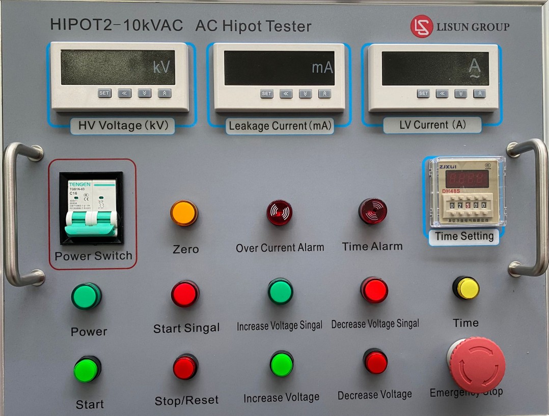
Panel Diagram (Image is for reference only; actual product may vary)
Power Switch: Main power switch;
HV Voltage: Displays the current actual high-voltage output voltage;
Leakage Current: Displays the current high-voltage leakage current;
LV Current: Displays the current actual low-voltage current;
Time Alarm: An alert that sounds when the set time has elapsed;
Overcurrent Alarm: Used to display an alarm notification when a breakdown occurs during the boost process;
Power: This indicator light turns on when the cabinet is powered on;
Time: Used to activate the time relay to measure the withstand voltage duration;
Time Setting: Setting the duration;
Start: Start the device;
Stop/Reset: Stops output; press the Stop button to reset;
Zero: During automatic voltage increase, press the stop button; when the voltage drops to the minimum, this indicator light turns on. When the voltage is manually reduced to the minimum, this indicator light turns on; when the withstand time is reached, and when the voltage is automatically reduced to the minimum, this light turns on;
Increase Voltage: Press this button to manually increase the voltage;
Decrease Voltage: Press this button to manually lower the voltage;
Start Signal: Stop indicator light;
Emergency Stop: Pressing this button cuts off all power to the device.
Increase Voltage Signal: Boost indicator light;
Decrease Voltage Signal: Voltage Drop Indicator;
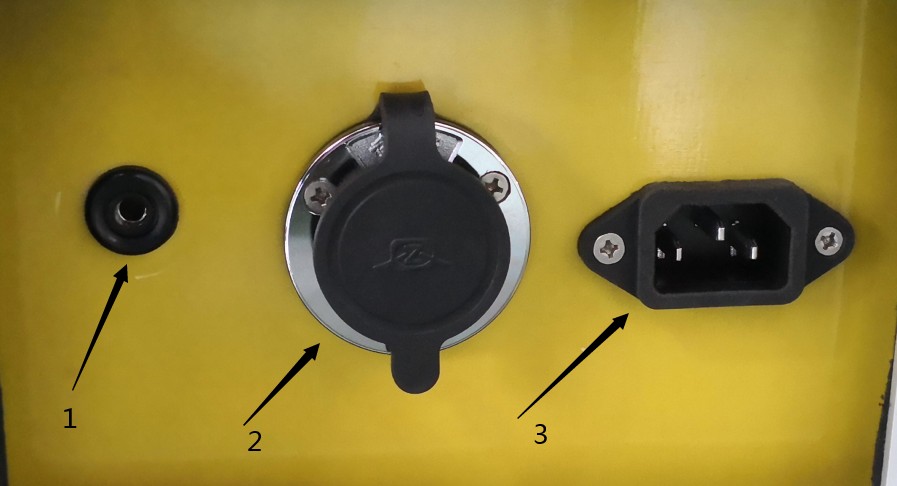
Rear Panel Diagram (Image is for reference only; actual product may vary)
Ground Terminal: Used for the protection and safety grounding of the equipment;
Output Control Signal Terminal: Used to supply a low-voltage input of 0–200 V to the Voltage Transformer and to sample a 0–100 V signal;
AC 220 V input power supply port: Connects to a 220 V power source to supply power to the device’s main circuit and control circuit;
Instructions for Using Digital Current and Voltage Meters
Meter Settings: The high-voltage voltmeter D1F is set for overvoltage, and D2F is set for the automatic voltage increase value.
4.1 Programming and Use
1. Descrierea panoului
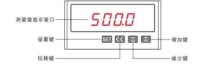
2. Descrieri butoane
SET button: Press the SET button to enter programming mode; in programming mode, use it to save and return to the menu item.
Shift key: In programming mode, use this key to exit programming mode when in a menu item; use it to move the cursor one position to the left when editing parameter values.

Down Arrow Key: In programming mode, use this key to scroll down through menu items when selecting them; when editing parameters,

When used as a numeric value, it is used to decrement the parameter value.
Increase Key: In programming mode, this key is used to scroll up through menu items when selecting them, and to increment parameter values when editing them.

3. Afișează instrucțiuni

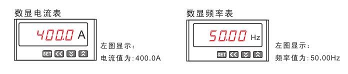
4. Meniu Descriere
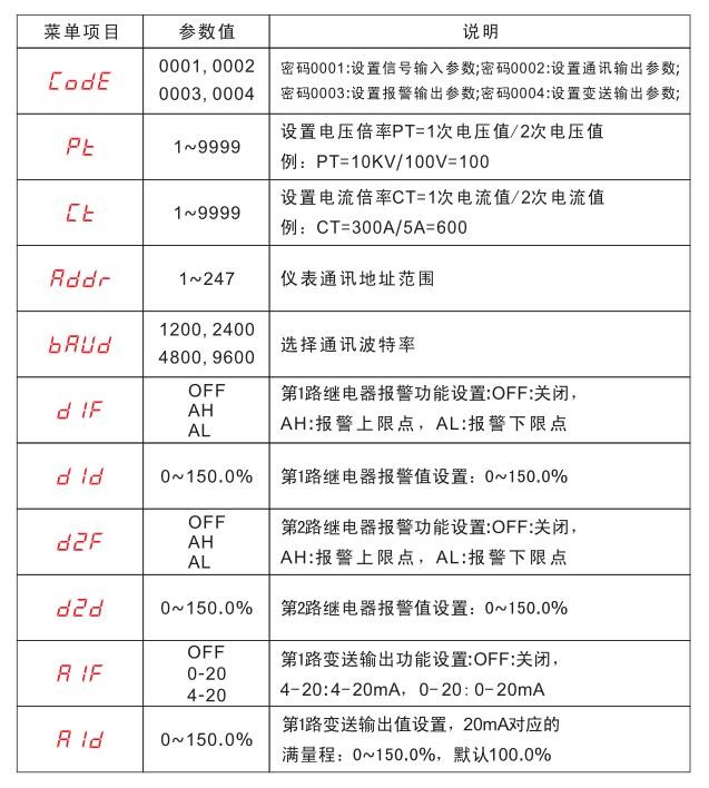
In programming mode, the instrument provides four menu items: signal input, communication output, digital alarm output, and analog transmitter output. The programming code for signal input is 0001; for communication output, it is 0002; for digital output, it is 0003; and for analog output, it is 0004.
The icons describing the menu options are shown below:
5. Programming Examples
Before using any meter for the first time, please verify that its parameters match those of the power distribution system in which it will be installed. The factory default settings are listed on the label on the back of each meter. If the parameters do not match, you can use the four buttons on the front panel to adjust the meter’s internal settings to meet the requirements of the power distribution system.
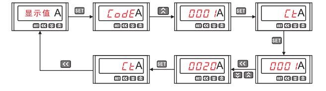
The factory specification for the AC digital ammeter is AC 5 A (CT = 1). If the user connects a 100 A/5 A current transformer, the CT parameter should be changed to 20 (CT = 100 A/5 A = 20).
The factory specification for the AC digital voltmeter is AC 10 kV/100 V (PT = 10 kV/100 V = 100). If the user switches to an external 35 kV/100 V current transformer, the PT parameter should be changed to 350 (PT = 35 kV/100 V = 350).

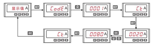
(3) The factory specification for the DC digital ammeter is DC 100 A/75 mV (CT = 100/5 = 20).if the user switches to an external 400 A/75 mV shunt, the CT parameter should be changed to 80 (CT = 400/5 = 80).
Instructions for Use and Precautions
1. Connect the power jack on the back panel to a 220V AC power source using a power cord.
One end of the test lead is connected to the backplane output, and the other end is connected to the test transformer;
Connect the ground wire to the backplane for grounding, and connect the other end to ground;
Connect one end of the high-voltage lead to the high-voltage terminal of the test transformer and the other end to the test specimen; check the connections, and after confirming they are correct, turn on the main circuit breaker for the 220 V AC mains power;
2. Turn on the main power circuit breaker, and rotate the emergency stop switch clockwise to release it. At this point, the digital displays for high-voltage, low-voltage, and leakage current will show readings, and the zero indicator light will illuminate; the power indicator light will illuminate;
Follow the instructions in Section IV, “Digital Display Meter User Manual,” or the instructional video to set the protection thresholds on the ammeter; set the time relay to the required withstand time;
After confirming that the settings are correct, press the start button. You will hear a “click” as the contactor engages. Press and hold the voltage-increase button to raise the voltage, and observe the high-voltage output display and the ammeter to see changes in their readings;
After the voltage has risen to the required value, release the voltage-boost button, press the timer button to perform the withstand voltage duration test, and the time relay will display the duration of the withstand voltage;
(Note: 1. Check the test site and the ammeter for any abnormalities. If any abnormalities are detected, immediately press the emergency stop button to stop the device. 2. If overcurrent protection is triggered for a test specimen, the protection buzzer will sound, indicating that the specimen has failed the test. Press the stop/reset button to silence the buzzer.)
However, once the withstand time has elapsed, the timer buzzer will sound, indicating that the test specimen has passed the withstand voltage test; press the timer button to stop the buzzer, and press and hold the voltage reduction button to reduce the voltage;
Once the voltage has dropped to zero and the indicator light comes on, press the Stop button, flip the main power switch on the side of the cabinet to the “Off” position to disconnect the AC 220 V mains power, and allow the test specimen to discharge. At this point, all test leads may be removed;
HIPOT Series Power Frequency Withstand Voltage Test Sets
1. Prezentare generală
This series of Voltage Transformers utilizes advanced production equipment and employs new manufacturing processes, such as epoxy vacuum casting of coil windings and CD-type cores. Compared to similar oil-immersed Voltage Transformers, they are significantly lighter and more compact, while improving insulation strength and moisture resistance, and effectively reducing stray magnetic flux, thereby significantly enhancing the Voltage Transformer’s ability to withstand the impact of test short-circuit currents.
This product series features a lightweight design, compact size, attractive appearance, stable performance, and ease of use and portability. It is particularly suitable for on-site operation and represents a new generation of AC/DC dual-purpose high-voltage Voltage Transformers in the domestic market. This series of products is suitable for on-site testing of the insulation performance of various electrical equipment in power systems and at power users’ sites, as well as for use as high-voltage power sources in various voltage systems or devices requiring low-current DC high-voltage testing of electrical products.
2. Specificații tehnice
Output Voltage Waveform: Sine Wave
No-load loss: 0.2%–0.35%
Impedance Voltage: 4.5%–8%
Surface temperature rise: <55°C
Permitted continuous operating time: 0.5 hours
Intermittent operating time: Continuous
3. Specificații tehnice cheie
| Specificații și modele | Capacitate (kVA) | Tensiunea de intrare (V) | Tensiune de ieșire (kV) | Curent de ieșire (mA) | DC High-Voltage Output (kV) | Maximum Overall Dimensions (mm) | Greutate (kg) |
| HIPOT-2/10 | 2 | 200 | 10 | 200 | 10 | ||
| HIPOT-1.5/50 | 1.5 | 200 | 50 | 30 | 70 | × × 240 180 380 | 13 |
| HIPOT-3/50 | 3 | 200 | 50 | 60 | 70 | × × 330 280 570 | 30 |
| HIPOT-6/50 | 6 | 200 | 50 | 120 | 70 | × × 400 330 670 | 48 |
| HIPOT-10/50 | 10 | 200 | 50 | 200 | 70 | × × 430 370 750 | 68 |
| HIPOT-15/50 | 15 | 200 | 50 | 300 | 70 | × × 470 370 750 | 82 |
| HIPOT-20/50 | 20 | 200 | 50 | 400 | 70 | × × 470 370 750 | 82 |
| HIPOT-2/100 | 2 | 200 | 100 | 20 | 140 | × × 330 280 650 | 52 |
| HIPOT-5/100 | 5 | 200 | 100 | 60 | 140 | × × 430 370 1100 | 76 |
| HIPOT-10/100 | 10 | 200 | 100 | 100 | 140 | × × 470 370 1100 | 77 |
| HIPOT-15/100 | 15 | 200 | 100 | 150 | 140 | × × 520 410 1150 | 90 |
4. Cum funcționează
This series of products has an input voltage of 200 V. By applying the principle of electromagnetic induction to adjust the input voltage as needed, the output voltage can be continuously adjusted from 0 V up to the maximum rated value.
When performing DC withstand voltage and leakage current tests, simply screw the high-voltage silicon stack onto the high-voltage output terminal to adjust the input voltage and obtain different DC high-voltage output values.
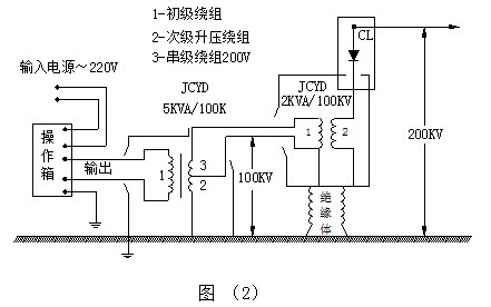
For the specific operating principle of this product series, see Figure (1). When used in a cascaded configuration, refer to Figure (2) for the wiring diagram.
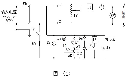
HIPOT: Voltage Transformer JS: Time relay
TY: Self-regulating Voltage Regulator FM: Alarm
LJ: Overcurrent relay D1, D2, D3: Indicator lights
C: AC contactor RD: Fuse
K: Main Power Switch K1: Time Relay Power Switch
AK: Voltage Regulator Return-to-Zero Limit Switch AQ: Start Button
CL: High-Voltage Silicon Diode Array AT: Stop Button
A: Output ammeter KV: Output voltmeter
5. Instrucțiuni de utilizare
(1) Before the test, the “ground” terminal on the Voltage Transformer’s enclosure and the “ground” terminal on the power control box must be properly grounded; otherwise, personal safety and equipment safety will be at risk.
(2) Before operating the equipment, you must be familiar with the electrical schematic diagrams of the high-voltage Voltage Transformer and the power control cabinet. When performing DC withstand voltage and leakage tests, you can first connect the high-voltage voltmeter or microampmeter to the high-voltage terminal of the high-voltage Voltage Transformer.
(3) Once preparations are complete and the wiring has been verified, close the main power switch; the red switch indicator light will then illuminate. If it does not light up, turn the Voltage Regulator knob counterclockwise back to the zero position; the indicator light on the red stop button will then illuminate. Otherwise, the start button will not function.
(4) Press the start button; the green indicator light will illuminate. At this point, rotate the Voltage Regulator knob slowly and evenly in a clockwise direction at a rate of 1.5–2 kilovolts per second. The high voltage will gradually increase; closely monitor the voltage meter reading and the condition of the test specimen until the desired test high voltage is reached.
(5) To test the product’s withstand voltage, set the timer to the desired duration and press the “Timer and Alarm” switch. This will test the product’s withstand voltage for the specified time, after which an alarm will sound. If the product under test breaks down, the overcurrent relay will automatically trip, at which point the reading on the voltmeter represents the product’s breakdown voltage.
(6) To protect the product under test from breakdown, first connect a protective spark gap in series on the high-voltage side and adjust the protective spark gap discharge voltage to approximately 1.15 times the test voltage.
(7) Schematic diagram of the high-voltage test:
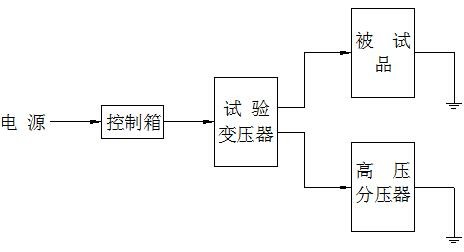
To ensure the safe and proper insulation testing of high-voltage electrical equipment, in addition to familiarizing yourself with this product’s manual, you must comply with relevant national standards and regulations, including GB/T 16927-1996 “High-Voltage Testing Techniques” and DL/T 596-1996 “Regulations for Preventive Testing of Power Equipment.”
Due to the design characteristics and structural limitations of this product series, continuous operation at the rated output capacity must not exceed two hours. If further use is required, turn off the power, wait two hours, and then turn it back on. Continuous operation is permitted at two-thirds of the rated voltage and two-thirds of the rated current.
In standard high-voltage electrical insulation applications, this series of products must not be operated at voltages exceeding the rated output voltage.
When using this series of products to set up a cascaded high-voltage test, pay special attention to inspecting the condition of the Voltage Transformers in stages 2 and 3 and their insulating supports, verifying the correctness of the connecting wires, and checking the protective grounding of the entire system and its grounding status.
Cerințe de siguranță:
Please read the following safety precautions to avoid personal injury and prevent damage to this product or any other products connected to it. To avoid potential hazards, this product must only be used within the specified limits.
To prevent fire or personal injury, maintenance may only be performed by qualified technicians.
Use the appropriate power cord. Use only the power cord designed specifically for this product and that meets its specifications.
Connect and disconnect properly. When the test leads are connected to live terminals, do not connect or disconnect them carelessly.
Product Grounding. In addition to grounding via the power cord’s grounding conductor, the grounding terminal on the product’s housing must be grounded. To prevent electric shock, the grounding conductor must be connected to ground. Before connecting to the product’s input or output terminals, ensure that the product is properly grounded.
Pay attention to the ratings of all terminals. To prevent the risk of fire or electric shock, observe all ratings and markings on this product. Before connecting this product, read the user manual to learn more about its ratings.
Do not operate the instrument without the cover plate in place. If the cover plate or front panel has been removed, do not operate this product.
Use the appropriate fuse. Use only fuses that meet the type and rating specifications for this product.
Avoid contact with exposed circuits and live metal parts. Do not touch exposed contacts or parts while the product is energized.
Do not operate the unit if you suspect a malfunction. If you suspect that this product is damaged, have it inspected by our service personnel; do not continue to operate it.
Nu utilizați în condiții de umiditate.
Do not operate in explosive environments.
Keep the product’s surface clean and dry.
Condiții de siguranță

Warning: Warning statements indicate situations or practices that may result in injury or death.
Caution: The word “Caution” indicates situations or practices that may result in damage to this product or other property.