
 Engleză
 中文简体
中文简体 Русский
 Español
 Português
 Türkçe
 العربية
 Deutsch
 Polski
 Italiano
 Français
 한국어
한국어 ไทย
ไทย Tiếng Việt
 日本語
日本語





























Tester cu ciocan de impact Pendulum IK
Manual de utilizare
Aplicabil LISUN modele: IK07-10,IK07-10S、IK07-11
1. Despachetarea și familiarizarea de bază cu echipamentul
1.1 Specificații tehnice cheie
|
Nivel IK |
Protection Rating Descriptions |
Energie de impact J |
Exemple de aplicații |
|
IK07 |
Resistant to heavy impacts (such as a 1-kg object dropped from a height of 1 meter) |
2 |
Commercial displays, elevator control panels, electrical distribution panels |
|
IK08 |
Resistant to severe impacts (such as a 2.5-kg object dropped from a height of 1 meter) |
5 |
Outdoor enclosures, heavy-duty machinery housings, charging stations |
|
IK09 |
Resistant to strong impacts (such as a 5-kg object dropped from a height of 1 meter) |
10 |
Heavy-duty industrial equipment, exterior vehicle components, explosion-proof junction boxes |
|
IK10 |
Resistant to severe impacts (such as a 7.5-kg object dropped from a height of 1 meter) |
20 |
Enclosures for explosion-proof equipment, mining machinery components, port equipment |
|
IK11 (Opțional) |
Resistant to extreme impacts (such as a 10-kg object dropped from a height of 1.2 meters) |
50 |
Housings for heavy industrial equipment, cabs for construction machinery, and protective enclosures for high-voltage equipment |
1.2 Despachetarea și verificarea conținutului
1.2.1 Despachetare și inspecție vizuală
When unpacking the device, handle it gently to avoid scratching the casing with sharp tools. After unpacking, first inspect the exterior of the device to ensure there is no visible deformation or dents, and that the buttons are not damaged or loose. If you find any damage or deformation to the device or its accessories, do not turn on the power and use it.
If you notice any issues, please contact us immediately.
1.2.2 Host Computer și Accesorii
IK Giant Swing Main Unit: 1 unit.
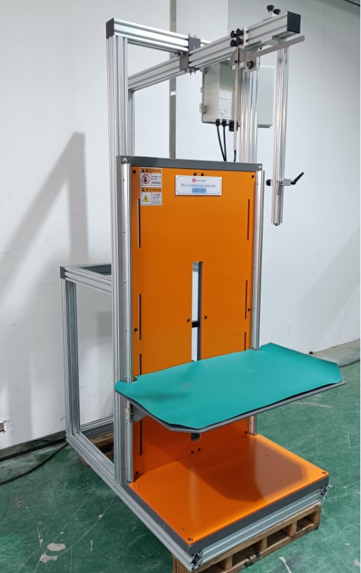
Figura 1
The standard main components are as follows: five impact hammers, used for testing at the IK07, IK08, IK09, IK10 și IK11 levels, respectively. There are also three pendulum rods: the thin rod is used for IK07, the medium rod for IK08, and the thick rod for IK09, IK10 și IK11.
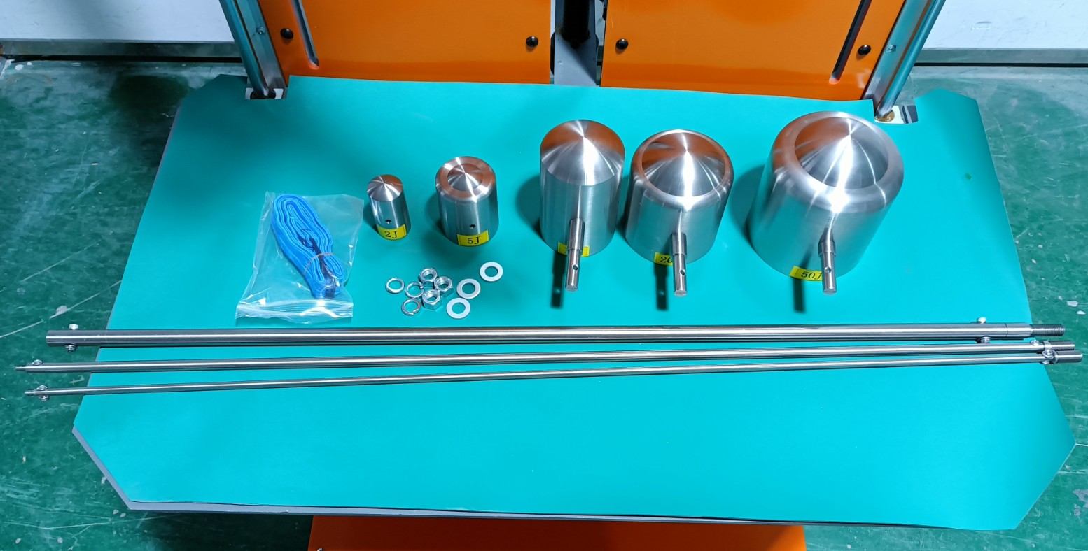
Figura 2
V-au fost trimise prin e-mail linkurile de descărcare pentru manualul de utilizare digital, cardul de garanție și alte documente. Vă rugăm să le descărcați cât mai curând posibil. Dacă ați pierdut e-mailul, nu ezitați să ne contactați pentru a solicita din nou linkurile de descărcare.
2. Măsuri de siguranță
2.1 Electrical Safety (The S model does not require a power connection)
2.1.1 Conexiune la alimentare
Alimentare monofazată de 220 V; prizele trebuie să respecte standardele de siguranță, să aibă o împământare corespunzătoare și un curent nominal care să corespundă cu puterea nominală a echipamentului.
2.1.2 Specificații de împământare
The equipment must be reliably grounded, with a grounding resistance of ≤4 Ω. Do not use gas pipes, non-metallic water pipes, or neutral wires as substitutes for grounding wires. After grounding is complete, use a Grounding Resistance Tester to measure the grounding resistance. Power may only be applied after confirming that it meets the requirements to prevent electric shock, equipment malfunctions, or measurement errors caused by poor grounding.
2.2 Siguranța operațională
You must wear impact-resistant gloves and safety goggles to prevent flying debris or ricochets from the impact hammer from causing injury;
Unauthorized personnel are prohibited from entering the test area to prevent accidental injury.
2.3 Siguranța mediului
The equipment must be installed in an air-conditioned room, with the ambient temperature maintained between 5°C and 35°C and relative humidity ≤ 85%.
The distance between the equipment and walls, as well as surrounding structures (such as other test equipment and shelves), must be at least 1000 mm pentru a facilita întreținere;
Părăsi cel puțin 2000 mm of space in front of the equipment to ensure that the swing arm can be raised properly and that there are no obstructions in the surrounding area;
The equipment must be placed on a level, solid surface with a levelness error of ≤0.5°.
2.4 Altele
Pentru aspectele care nu sunt acoperite de acest manual, vă rugăm să procedați cu prudență sau să ne contactați.
3. Pregătiri înainte de test
3.1 Sample Requirements
The housing of the test specimen must be clean, brand-new, and intact, with all components properly installed, in accordance with the product’s factory-shipped condition;
If specified in the product standard, samples must be pretreated (e.g., powered on, or simulated to mimic the operating state of moving parts); if no such specifications exist, prepare the samples under normal temperature and pressure conditions.
3.2 Punerea în funcţiune a echipamentelor
3.2.1 Powering On the Device (This step does not apply to the S model)
Turn on the two switches inside the chassis shown in the figure below.
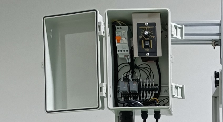
Figura 3
3.2.2 Installation of the Swing-Arm Impact Hammer
Select the impact hammer and pendulum arm with the required IK rating according to section 1.2.2. Install and secure the pendulum arm:
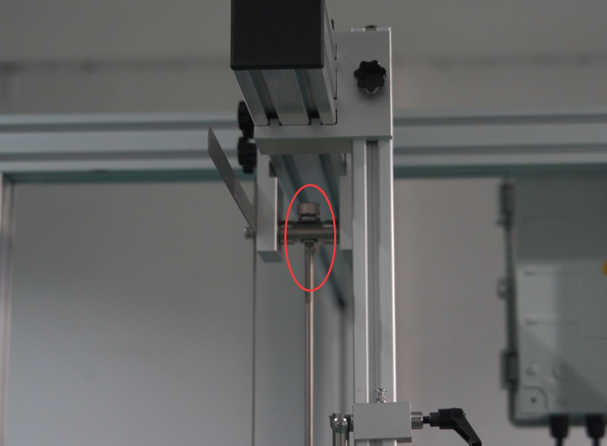
Figura 4
Install and secure the impact hammer:
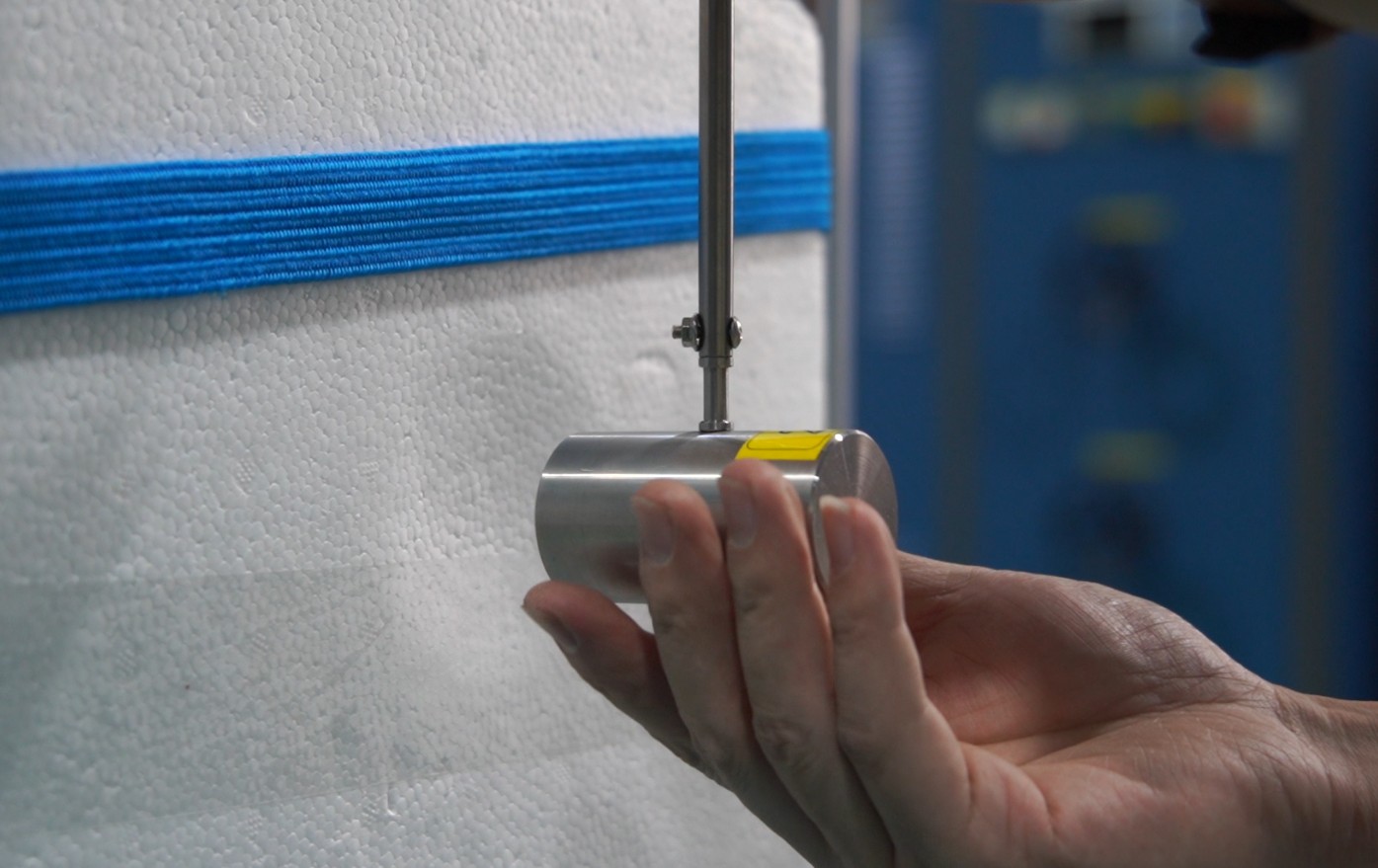
Figura 5
If necessary, rotate the swing arm so that the direction of the impact hammer head aligns with the direction of the swing arm’s movement. After readjusting, secure the swing arm again.
3.2.3 Sample Mounting and Alignment
Determine the test surfaces: Give priority to the weakest points in the product design; if there are no specific requirements, distribute the impact points evenly across each surface, with each surface subjected to 5 impacts (no more than 3 impacts in the vicinity of the same location).
Place the sample on the test stage close to the device’s backplane, with the test surface facing the impact hammer. Adjust the height of the test stage using the height adjustment switch based on the elevation of the test point:
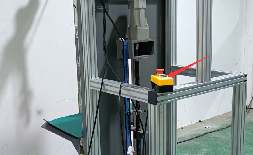
Figura 6
If you have the S model, you’ll need to use the hand-crank to adjust the stage to the appropriate height:
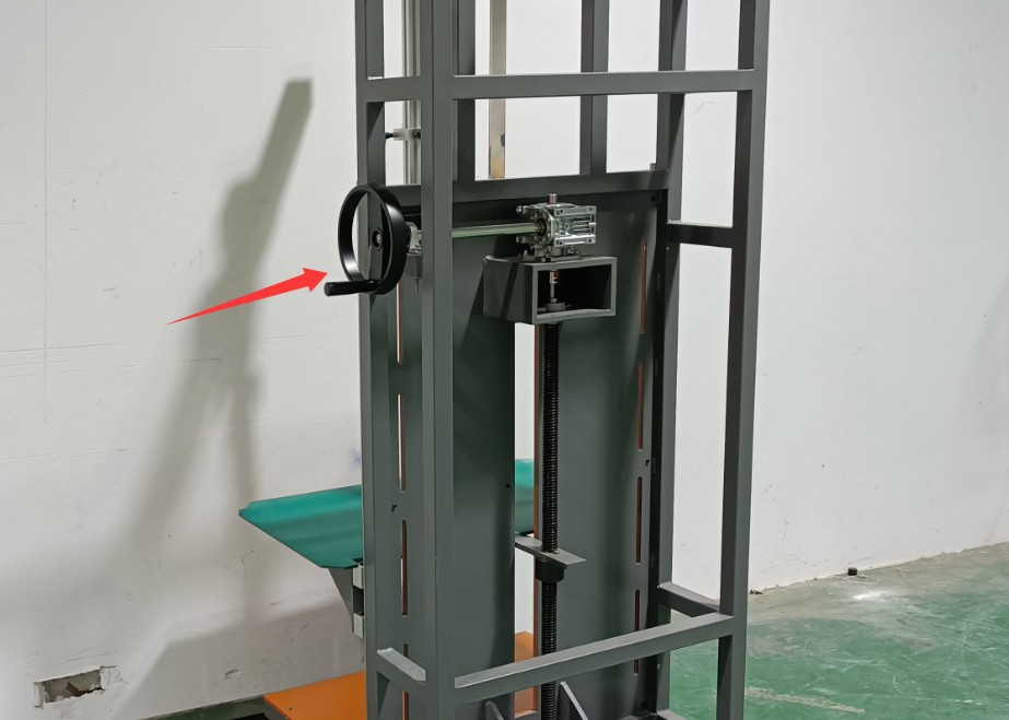
Figura 7
Depending on the thickness of the sample, loosen the mounting screws on the module shown in the figure below and move the entire unit:
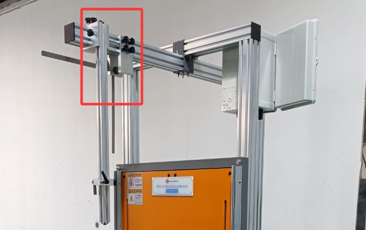
Figura 8
Move it so that the impact hammer just touches the test point when it hangs naturally, and then tighten the set screw:
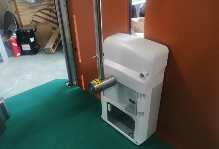
Figura 9
Then secure the specimen with a flexible strap to prevent the attachment points from obscuring the test surface and to ensure that the specimen does not shift during the impact.
4. IK Rating Test Procedures
4.1 Height Requirements for the Impact Hammer
The IEC 60068-2-75 (GB/T 2423.55) standard specifies the following IK ratings and drop heights:
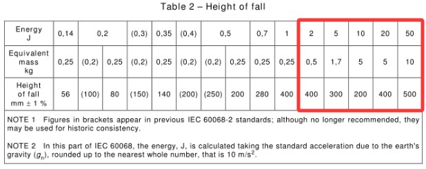
Figura 10
Specifically, the drop heights for IK07, IK08, IK09, IK10 și IK11 are 400 mm, 300 mm, 200 mm, 400 mm, and 500 mm, respectively.
The height of the IK giant pendulum can be determined using the protractor shown in the figure below:
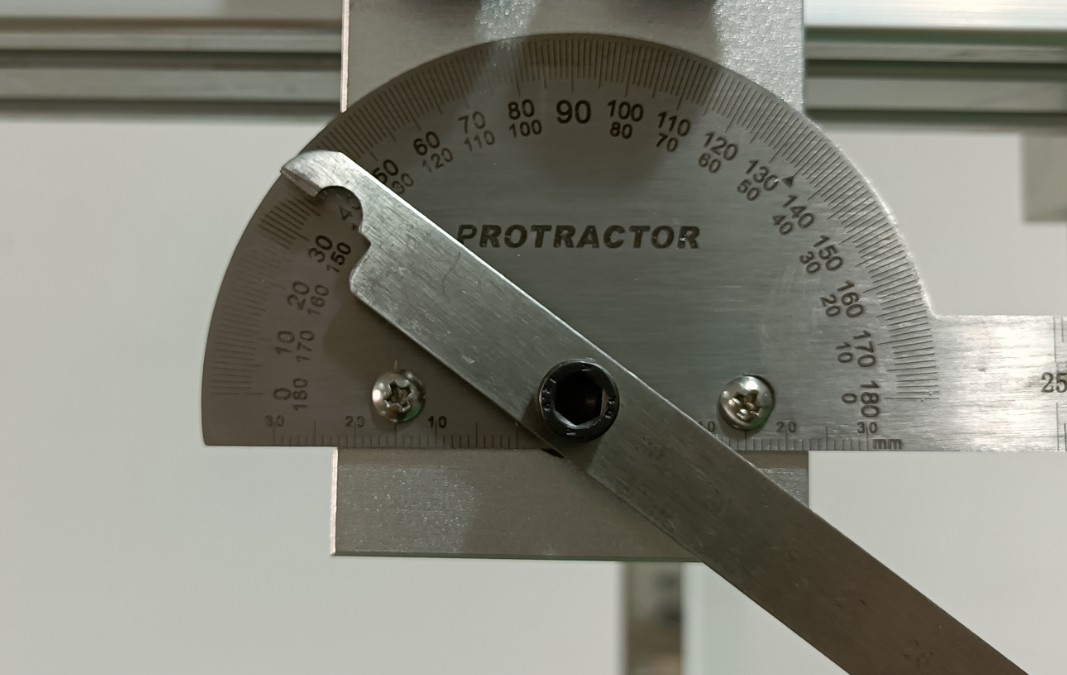
Figura 11
The graph showing the relationship between angle and height is as follows:
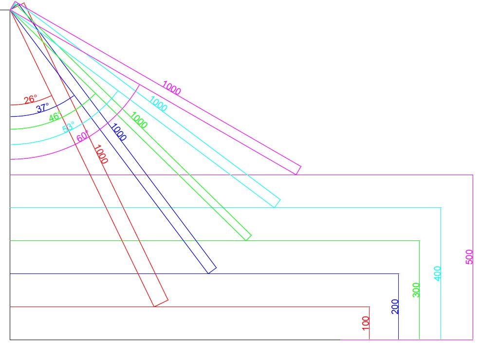
Figura 12
4.2 Impact Hammer Height Setting
Luare IK10 as an example, the required drop height is 400 mm, which means the pendulum arm must be raised to an angle of 53° from the vertical—that is, the protractor should read 90° – 53° = 37°. Then, use the slider marked in the figure below to secure the pendulum arm.
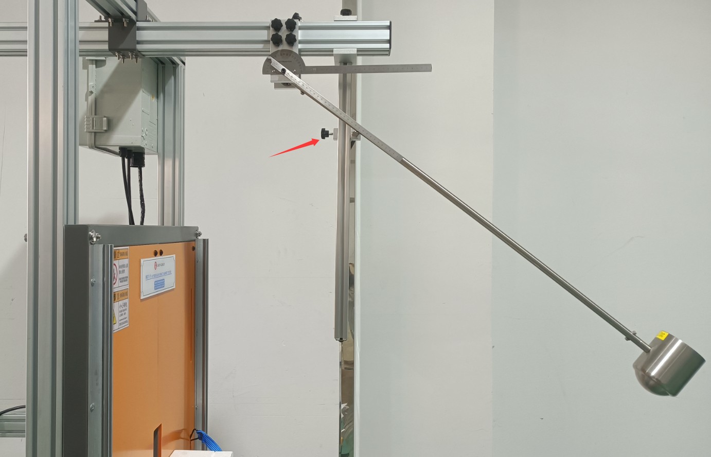
Figura 13
4.3 IK Impact Test
As shown in the figure below, turn the handle opposite the slide to release the impact hammer and perform the impact test.
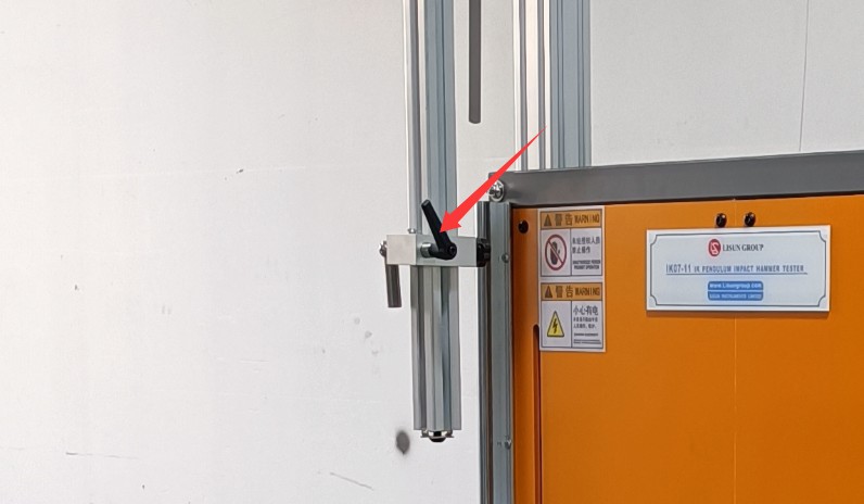
Figura 14
To prevent the impact hammer from striking repeatedly due to inertia, after the impact hammer completes a strike and rebounds, you must manually hold the impact hammer and slowly return it to its original position. Do not use your hands to directly grip the swing arm to stop it (as this can easily cause the swing arm to deform).
Adjust the position of the sample and continue conducting impact tests on the other test points until the entire test is complete.
5. Proceduri post-test
5.1 Equipment Shutdown and Reset
Turn off the power switch (not necessary for the S model);
If testing is not to be continued on the same day, remove the impact hammer and pendulum to prevent deformation of the pendulum, clean them, and store them separately in a safe place (avoid impact).
5.2 Pregătirea și observarea probei
Visual inspection: Check the sample housing for cracks, dents, or peeling, and check whether any fasteners are loose;
Functional Testing: Power on the sample to verify that all functions are operating normally and that there are no malfunctions;
Determine whether the product meets the IK rating requirements based on the product standards, and record the test results (pass/fail).
5.3 Pregătirea mediului de testare
Clean the equipment surfaces: Wipe down the test fixture, stage, and impact hammer with a dry cloth to remove dust and grease. Do not use water or corrosive cleaning agents;
Curățați zona de testare: Îndepărtați orice resturi de probă (dacă există), organizați uneltele și accesoriile și mențineți zona curată și ordonată.
5.4 Long-Term Storage and Maintenance (When Not in Use for More Than 1 Month)
Component Storage: After cleaning the impact hammer and swing arm, apply rust-preventative oil and place them separately in their packaging to prevent impact;
Equipment Protection: Cover with a dust cover; store in a dry, well-ventilated environment at a temperature of 5–35°C and a humidity of ≤60%;
Regular Power-On: For the electric model, power it on once a month and operate the stage lift function 5 to 10 times to prevent the motor from getting damp.
6. Troubleshooting and Resolving Common Problems
6.1 Defecțiuni mecanice
6.1.1 The swing arm cannot be locked or released
Cause of the malfunction: The locking handle screw is loose; debris is jammed in the locking mechanism;
Troubleshooting: Check the screws securing the locking handle and tighten any loose ones; remove dust and debris from the locking mechanism;
Test Results: The locking handle securely holds the swing arm in place, and there is no sticking when released.
6.1.2 Impact Ciocan Striking Deviation
Causes of failure: The sample was not securely fastened; the stage height was not adjusted properly; the impact hammer was installed off-center;
Troubleshooting steps: Re-secure the specimen to ensure it does not shift; recalibrate the alignment between the impact hammer and the specimen’s test point; check whether the connection between the impact hammer and the pendulum is centered;
Test Result: Deviation between the center point of impact and the test point ≤ 2 mm.
6.1.3 Bending Deformation of the Swing Arm
Cause of Failure: Incorrect braking method after impact (gripping the swing arm); deformation due to prolonged exposure to stress without removing the impact hammer;
Inspection Method: Visually check whether the swing arm is straight; use a straightedge to measure the curvature—a value greater than 0.5 mm indicates deformation;
Solution: Contact customer service to have the swing arm replaced; do not continue using the product (as this will cause energy deviations).
6.2 Electrical Malfunctions (No electrical section in the S model)
6.2.1 The stage cannot be raised or lowered
Cause of malfunction: Power not connected; lift switch malfunction; motor failure;
Troubleshooting steps: Check the power plug and switch to ensure power is connected; press the lift switch to see if you hear the motor running (if there is no sound, the switch or motor may be faulty);
Troubleshooting: Unplug and plug the power cord back in, or try a different outlet; if the switch is faulty, contact customer service to have it replaced; if the motor is faulty, professional repair is required.
6.2.2 Stuttering Stage Movement
Cause of the malfunction: Lack of lubricating oil in the lifting mechanism; foreign objects causing a jam;
Troubleshooting Steps: Check the lift guide rails for dust or debris; listen for unusual noises during operation;
Solution: Remove any debris and apply an appropriate amount of grease; if it continues to stick, contact customer service to have the guide rail inspected.