
 Engleză
 中文简体
中文简体 Русский
 Español
 Português
 Türkçe
 العربية
 Deutsch
 Polski
 Italiano
 Français
 한국어
한국어 ไทย
ไทย Tiếng Việt
 日本語
日本語





























Tester de imunitate la câmp magnetic la impuls
Manual de utilizare
Aplicabil LISUN modele: IMF61000-9,IMF61000-9A
1. Noțiuni de bază despre echipament
1.1 Specificații tehnice cheie
| Model | IMF61000-9 | IMF61000-9A |
| Iesire de curent | 100–1200 A/m ± 10% | 100–3000 A/m ±10% |
| Forma de undă a curentului de scurtcircuit | 6.4 μs ± 30%, 16 μs ± 30% | |
| Forma de undă a tensiunii de pornire | 1.2 μs ± 20%, 50 μs ± 20% | |
| Impedanță de ieșire | 2 Ω ± 0.25 Ω | |
| Polaritatea de ieșire | Terminal pozitiv, terminal negativ și complet automat | |
| Bobină de câmp magnetic | 1 x 1 m single-turn coil | |
| Sistem de control | 10-inch Extra-Large Chinese-English Android Touchscreen | |
1.2 Verificarea configurației echipamentului
1.2.1 Despachetarea
When unpacking the device, handle it gently to avoid scratching the outer casing with sharp tools. After unpacking, first inspect the exterior of the device to ensure there are no visible deformations or dents and that the buttons are not damaged or loose. If you notice any abnormalities with the device or its accessories, do not turn it on. Please contact us immediately.
1.2.2 Unitatea principală și accesoriile
Echipament principal: IMF61000-9 Impulse Magnetic Field Immunity Tester, pulsed magnetic field coils, and mounting brackets.
For other standard accessories, see Figure 1-1.
| Număr | notițe |
| ① | Cablu de alimentare |
| ② | Pulse Magnetic Field Coil Connecting Wires |
| ③ | Cablu de împământare, utilizat pentru conectarea la terminalul de împământare de protecție PGND |
| ④ | Coaxial cable, used to connect an external oscilloscope to view waveforms |
| ⑤ | Discharge tube, a specialized component for equipment troubleshooting, used to help determine whether the main unit is generating a pulsed magnetic field |
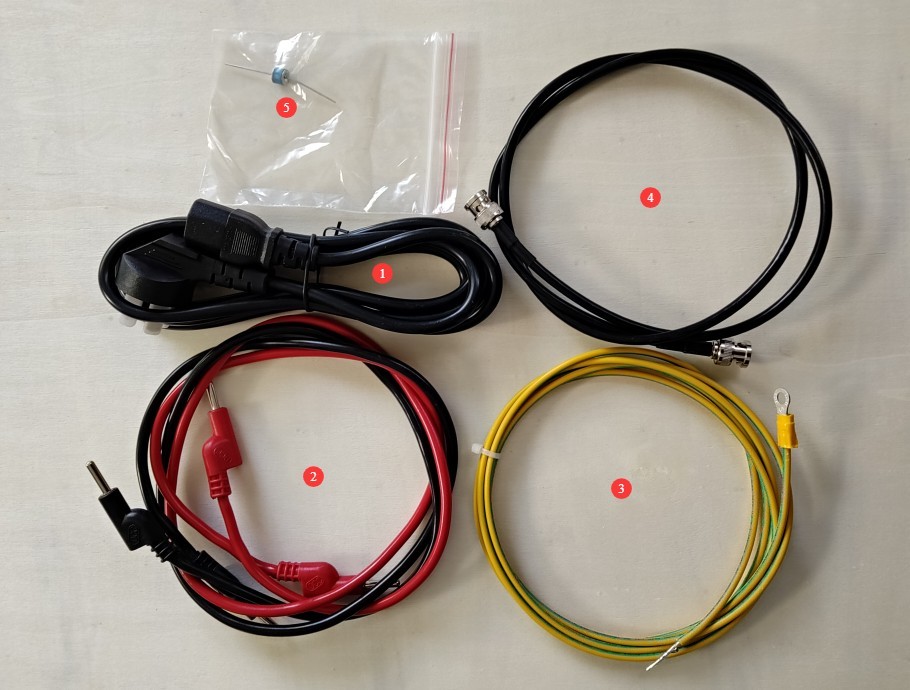
Figura 1-1
1.2.3 Descărcarea documentelor electronice
We have already sent you the download links for the electronic user manual, software, warranty card, and other materials via email at the time of shipment. Please download them as soon as possible. If you have not received the email, please contact us to obtain the download links again.
1.3 Scopul principal al echipamentului
This equipment complies with GB/T 17626.9-2025, IEC 61000-4-9:2016 standards for pulsed magnetic field immunity testing. It can simulate pulsed magnetic field interference generated by the operation of power switches and induced by lightning strikes, and is used to evaluate the magnetic field immunity of electronic and electrical equipment.
2. Măsuri de siguranță
2.1 Electrical Safety for Equipment
Verify that the equipment’s power supply voltage matches the mains voltage (AC 220 V ±10%, 50/60 Hz), and ensure that the power supply is properly grounded and that the grounding wire is not damaged or loose.
2.2 Environmental Operations Safety Standards
2.2.1 Temperature and Humidity Restrictions
Do not turn on the equipment when your hands are wet or when the ambient relative humidity exceeds 75%; do not use the equipment in environments exposed to rain, condensation, or excessive dust concentrations.
2.2.2 Site Safety Requirements
The area where the equipment is placed must be reliably grounded and located away from metal walls; warning signs must be posted in the test area, and non-operators are prohibited from approaching the test coil and high-voltage output terminal.
2.3 Safety Guidelines for High-Voltage Operations
2.3.1 Wiring Replacement Specifications
This equipment features a high-voltage pulse output. Before changing the wiring at the pulse terminals, ensure that the HV indicator light is completely off before proceeding. Never plug in or unplug test cables, synchronization signal ports, or current sampling ports while the equipment is energized.
2.3.2 Operational Contraindications
The equipment carries high voltage internally while in operation. Do not disassemble the equipment or operate it with the housing open; non-professionals must not open the equipment housing. When the equipment is unloaded, do not leave the high voltage on for extended periods or continuously trigger the vacuum contactor, to avoid shortening the service life of the switch.
Do not eat or drink while the equipment is undergoing test operation to prevent respiratory obstruction caused by accidental electric shock; do not touch the pulse output terminal, coil terminals, or high-voltage connectors on the rear panel with your bare hands during operation.
3. Equipment Hardware Overview and Wiring
3.1 Vedere frontală
3.1.1 Overall Connection
Vezi Figura 3-1.
| Număr | notițe |
| ① | IMF61000-9 Tester de imunitate la câmp magnetic la impuls |
| ② | Suport bobină |
| ③ | Pulsed Magnetic Field Coil |
| ④ | Coil Connecting Wires |
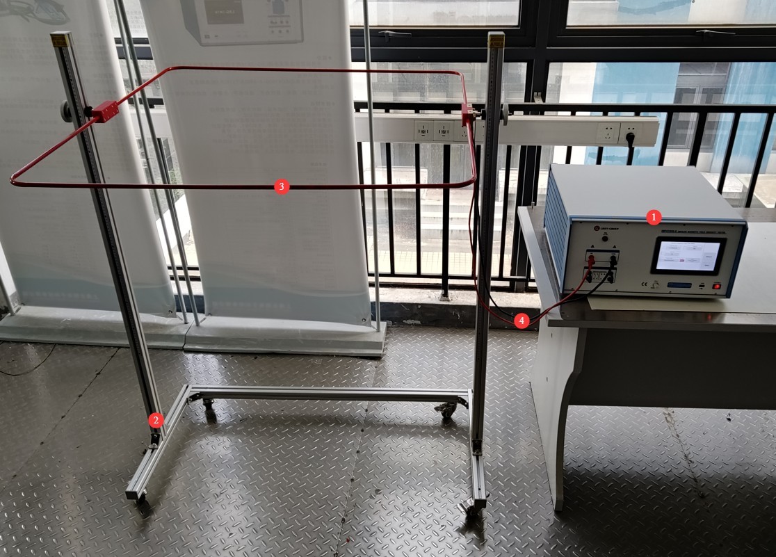
Figura 3-1
3.1.2 Introduction to the Front Panel of The Impulse Magnetic Field Immunity Tester
Vezi Figura 3-2.
| Număr | notițe |
| ① | Întrerupător |
| ② | It can be used to connect a USB mouse to control the touchscreen, or to connect a USB flash drive to update the operating system. |
| ③ | Current sampling port, 1000:1 ratio, for use with external waveform monitoring devices such as oscilloscopes |
| ④ | Touchscreen |
| ⑤ | HV High-Voltage Indicator Light |
| ⑥ | Pulsed magnetic field output, connected to the pulsed magnetic field coil |
| ⑦ | Synchronization Signal Sampling: When the U-shaped plug is inserted in the default orientation, the phase angle of the sampling device’s power input is sampled; that is, the phase angle of the device’s power input matches that of the EUT’s power input by default. If you need to directly sample the phase angle of the EUT’s power input, connect one end of the synchronization signal line to the instrument’s synchronization signal sampling terminal and the other end to the EUT’s power input terminal. |
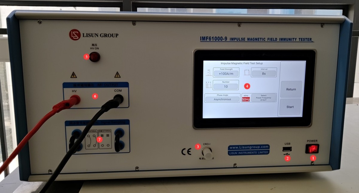
Figura 3-2
3.2 Introduction to and Wiring of The Impulse Magnetic Field Immunity Tester’S Rear Panel
Vezi Figura 3-3.
| Număr | notițe |
| ① | Power cord receptacle, with fuse |
| ② | RS-232 interface: If you have custom remote control functionality, you can connect it to a computer using an RS-232 cable. |
| ③ | PGND: Protective ground terminal; connect to ground using a ground wire. |
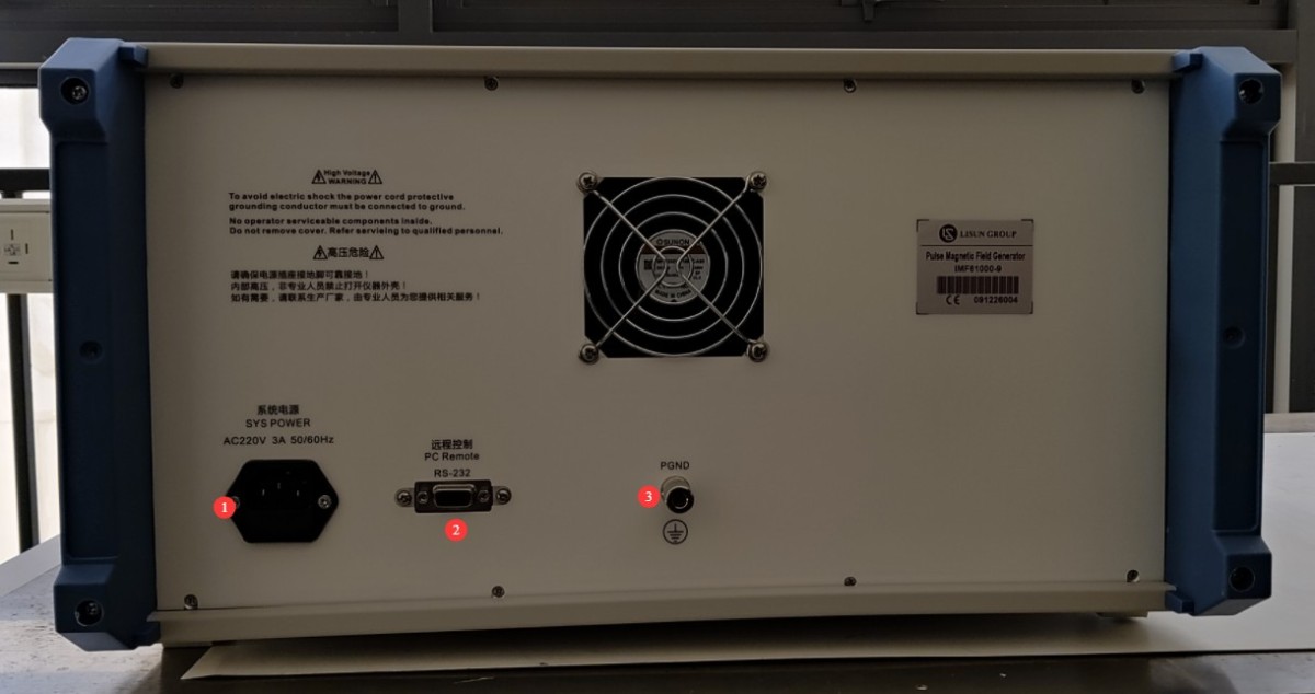
Figura 3-3
4. Introducere în programul cu ecran tactil
4.1 Ecranul de pornire a programului
Vezi Figura 4-1.
| Număr | notițe |
| ① | Reguli generale de utilizare (Această funcție este încă în curs de dezvoltare; vă rugăm să nu o accesați și să nu efectuați nicio acțiune în acest moment) |
| ② | Ecranul cu informații despre sistem |
| ③ | Comutați între chineză și engleză |
| ④ | Pulsed Magnetic Field Test Interface |
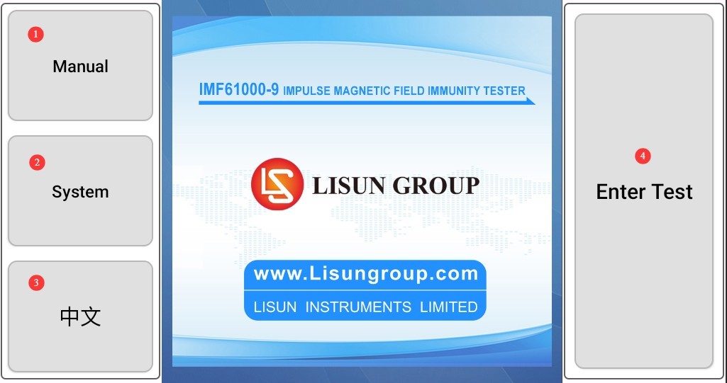
Figura 4-1
4.2 Pulsed Magnetic Field Test Interface
Vezi Figura 4-2.
| Număr | notițe |
| ① | Set the magnetic field strength and polarity |
| ② | Set the interval; the standard test recommends an interval of 10 to 30 seconds to meet the requirements for repeated pulse application. |
| ③ | Set the number of discharge cycles; for standard testing of conventional products, 10/50 cycles are recommended. |
| ④ | Set the discharge phase angle; when synchronous testing is not required, the default setting is asynchronous triggering (independent of the power line phase). |
| ⑤ | Selecting the EUT Power Supply Frequency |
| ⑥ | Click to start/stop the magnetic field pulse test |
| ⑦ | Reveniți la ecranul de pornire |
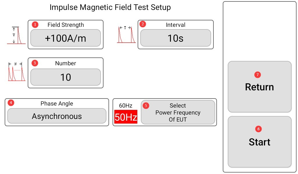
Figura 4-2
5. Arrangement of the EUT and Test Bench
5.1 Test Environment Standards and Requirements
5.1.1 Basic Environmental Conditions
Strictly adhere to the standards: ambient temperature 10°C to 35°C, humidity 10% to 65% RH, and no additional sources of electromagnetic interference at the test site.
5.1.2 Electromagnetic Environment Requirements
The test area must be located away from sources of interference such as variable-frequency drives, relays, and high-power motors, and must be at least 0.5 m away from metal walls, floors, and large metal structures.
5.2 Placement Guidelines for the EUT (Equipment Under Test)
5.2.1 Desktop EUT Layout
Place the equipment under test (EUT) on a non-conductive, insulated test bench with no exposed metal framework; the EUT must undergo testing with pulsed magnetic fields applied in the X, Y, and Z dimensions, adjusting the equipment’s orientation each time.
5.2.2 Floor-Standing EUT Arrangement
A reference ground plane (RGP) must be installed, consisting of galvanized steel or copper sheet with a thickness of ≥0.65 mm and dimensions of ≥1 m × 1 m; the EUT must be electrically isolated from the ground plane, positioned at a height of ≥0.75 m above the floor, and the coils must be placed at a height of no less than 0.5 m.
5.3 Requirements for the Arrangement of Pulse-Sensitive Coils
5.3.1 Coil Spacing Specifications
The standard coil must be maintained at the standard test distance from the EUT’s surface and positioned strictly in accordance with the standard’s requirements for a uniform magnetic field; the coil must not be placed near any metal objects to prevent magnetic field distortion from affecting test accuracy.
5.3.2 Adjusting the Coil Orientation
Adjust the coil in sequence so that it faces the front, side, and back of the EUT, as required by the standard, to complete the omnidirectional pulsed magnetic field test.
5.4 Auxiliary Cables and Grounding Arrangements
5.4.1 Dirijarea cablurilor
The EUT’s power and signal cables must be neatly arranged along the edge of the test bench; they must not be wrapped around the test coils, and their lengths must comply with standard specifications.
5.4.2 Grounding Arrangement
Both the test bench and metal auxiliary fixtures must be reliably grounded, with a grounding resistance of ≤1 Ω, in compliance with EMC laboratory grounding specifications.
6. Pulse Magnetic Field Testing Procedures
6.1 EUT Pretreatment
Power on the EUT and allow it to warm up until it reaches a stable operating state (typically 5 to 10 minutes; refer to the equipment manual); record the EUT’s initial operating state (indicator lights, communication, display, output functions, etc.).
6.2 Equipment Startup Procedure
Press the power switch on the front panel of the device to turn it on. The touchscreen will automatically light up and display the initial screen. Wait for the device to complete its self-test (approximately 10 seconds); if no errors are reported, proceed to the next step.
6.3 Standard Configuration of Test Parameters
6.3.1 Set the field strength according to the standard level
Classified according to standard product test grades: Civilian Grade 100–200 A/m, Industrial Grade 300–600 A/m, and Power Grade 800–1200 A/m.
6.3.2 Default Settings for General Parameters
Discharge Interval: Set to 15 seconds (standard default value); Number of Discharges: Set to 30 (basic compliance test); Output Polarity: Positive, Negative, Positive-Negative Alternating; Trigger Mode: Set to asynchronous trigger for routine testing.
6.3.3 Configuring Synchronization Test Parameters
If the product standard requires phase synchronization, enable automatic phase mode and select the 0°/90°/180°/270° cycle mode.
6.4 Startup and Operational Testing
6.4.1 Test de pornire
After confirming that all parameters have been set correctly, tap the touchscreen to start the test. The device will automatically activate the high voltage, and the HV indicator light will illuminate, outputting a pulsed magnetic field according to the set parameters.
6.4.2 Monitorizarea procesului în timp real
Observe the counting and timing status on the touchscreen to verify that pulses are being triggered normally; monitor the EUT’s operating status throughout the entire process and record any occurrences of system freezes, malfunctions, communication errors, display failures, or other issues.
6.4.3 Mid-Process Interventions
If an EUT anomaly or equipment alarm occurs during the test, immediately click to terminate the test and stop the pulse output.
6.5 Multidimensional Repetition Testing
6.5.1 Orientation Switching Test
After completing the unidirectional test, first terminate the test and turn off the high voltage, then adjust the orientation of the EUT and the coil, and repeat the parameter settings and test procedure.
6.5.2 Polarity Retest
In accordance with the product standards, switch between positive and negative polarity to complete the full-polarity pulsed magnetic field test.
7. Proceduri post-test
7.1 Testing Shutdown Procedures
7.1.1 Normal Shutdown
Once the specified number of tests has been completed, the device automatically stops outputting pulses and waits for the high-voltage indicator light to turn off completely (approximately 15 seconds).
7.1.2 Manually Ending a Shutdown
After terminating the test prematurely, wait until the high voltage has been fully discharged and confirm that no residual high voltage remains before proceeding with subsequent operations.
7.2 Standard Equipment Power-Off Procedure
7.2.1 Shutdown Procedure
Exit the touchscreen test screen to return to the home screen; press the power switch on the front panel to turn off the unit.
7.2.2 Guidelines for Removing Sutures
After the power has been turned off for approximately 30 seconds, disconnect the test coil connection cables and the synchronization signal sampling cables in that order; organize and store the cables in the provided accessory box. Do not drag or pull on the cables.
8. Întreținerea și îngrijirea zilnică a echipamentelor
8.1 Cleaning and Maintenance During Daily Use
8.1.1 Cleaning the Airframe
After each test, wipe down the equipment housing and touchscreen with a dry, lint-free soft cloth. Do not spray water or alcohol directly onto the machine.
8.1.2 Maintenance of Interface Contacts
Clean dust from the front and rear panel ports once a month, and use a dry brush to clean the terminals to prevent oxidation and poor contact.
8.2 Storage and Maintenance During Downtime
8.2.1 Short-Term Idle Period (1–30 days)
Store in a dry environment free of dust and corrosive gases, and ensure a proper ground connection.
8.2.2 Long-term inactivity (more than 30 days)
Disconnect all external cables, cover the entire device with a dust cover, and store it in an environment with a temperature of 5–40°C and humidity below 70% RH. Power on the device for 30 minutes each month to remove moisture.
8.3 Maintenance of Consumables and Accessories
8.3.1 Test Cable Maintenance
Avoid kinking or crushing the cables; do not pull on the terminal connectors; replace immediately if the outer sheath is damaged.
8.3.2 Maintenance of Induction Coils
Do not allow the coil to be bumped or exposed to water. Store it away from magnetic objects to prevent shifts in coil parameters from affecting test accuracy.
8.4 Cerințe privind intervalul de calibrare
Pentru a asigura acuratețea măsurătorilor și fiabilitatea operațională a echipamentului, se recomandă trimiterea periodică a acestuia la un laborator de metrologie terț calificat pentru calibrare. Intervalul de calibrare recomandat este de 12 luni. Utilizatorii pot determina intervalul specific de calibrare în funcție de frecvența de utilizare, condițiile de mediu și cerințele sistemului de calitate.
9. Depanarea și rezolvarea problemelor comune
| Simptome de eroare | Cauze posibile | Procedură |
| Nu se poate porni | Cablu de alimentare slăbit, siguranță arsă | Turn off the power and check the connection of the input power supply cord; turn off the power, troubleshoot for short circuits or overloads, replace the fuse with one of the same rating, and do not increase the current rating. |
| Large fluctuations in the output electric field strength | Loose terminal connections, excessive ambient humidity, poor grounding | Tighten all connections; reduce the ambient humidity; re-establish a reliable ground connection |
| The high-voltage indicator light stays on | High-voltage discharge circuit malfunction; residual charge not discharged | Immediately turn off the power and let it sit for 5 minutes. Do not touch the high-voltage side. Turn the power back on and try again. If the problem persists, contact us for repair. |