
 Engleză
 中文简体
中文简体 Русский
 Español
 Português
 Türkçe
 العربية
 Deutsch
 Polski
 Italiano
 Français
 한국어
한국어 ไทย
ไทย Tiếng Việt
 日本語
日本語





























Dispozitiv de testare a solicitărilor electrice și termice
Manual de utilizare
Aplicabil LISUN modele: JCY-1
1. Unboxing and Basic Understanding of the Equipment
1.1 Specificații tehnice cheie
| parametrii | notițe |
| Curent de testare | 0-30 A |
| Setting the Number of Trials | 0-9999 ori |
1.2 Inspecția despachetării și verificarea accesoriilor
1.2.1 Despachetare și inspecție vizuală
When unpacking the device, handle it gently to avoid scratching the exterior casing with sharp tools. After unboxing, first inspect the exterior of the device to ensure there is no visible deformation or dents, and that the buttons are not damaged or loose. If you notice any abnormalities with the device or its accessories, do not turn it on. Please contact us immediately.
1.2.2 Unitatea principală și accesoriile
| Număr | notițe |
| ① | JCY-1 Electrical and Thermal Stresses Test Device |
| ② | Cablu de alimentare |
Download links for the digital user manual, software, warranty card, and other materials have been sent via email. Please download them promptly. If you missed the email, you may contact us to request the download links again.
1.3 Domeniul de aplicare al echipamentului
Acest echipament este proiectat în conformitate cu clauza 12.3.11 din GB/T 2099.1 (IEC 60884-1) and Clause 12.3.11 of GB/T 16915.1 (IEC 60669-1). By applying a test current, the equipment simulates the electrical and thermal stress conditions that terminals encounter during actual use over a set cycle period and is capable of performing multiple cycle tests.
Acest manual se referă la clauza 12.3.11 din standardul GB/T 16915.1 (IEC 60669-1). Vă rugăm să rețineți acest lucru dacă trebuie să consultați alte standarde și cerințele de testare diferă.
2. Măsuri de siguranță
2.1 Siguranța electrică
2.1.1 Cerințe privind alimentarea cu energie electrică
Folosiți o priză monofazată cu trei pini, 220 V ±10%, 50/60 Hz; pinul de împământare trebuie conectat la împământare. Nu împărțiți priza cu echipamente de mare putere pentru a evita fluctuațiile de tensiune care ar putea interfera cu testul.
2.1.2 Cerințe de împământare
Firul de împământare al instrumentului este conectat fiabil la firul de împământare de protecție, iar rezistența la împământare de protecție este ≤4 Ω.
2.2 Siguranța mediului
2.2.1 Cerințe de temperatură și umiditate
Evitați utilizarea dispozitivului în medii în care umiditatea depășește 70% (fără condens) sau în care temperatura este în afara intervalului 0–35°C. Temperatura optimă de funcționare este de 25±2°C.
2.2.2 Contraindicații legate de mediu
Medii cu câmpuri magnetice puternice și câmpuri electrice puternice;
Medii care conțin gaze sau lichide corozive;
Zone cu praf inflamabil și exploziv și zone care conțin materiale periculoase;
Medii cu praf intens, temperaturi și umiditate ridicate și expunere directă la lumina soarelui.
2.3 Siguranța operațională
Operators must be familiar with the instruction manual and wear insulating protective gear;
A dedicated staff member is on duty throughout the entire testing process to strictly prevent the risk of overheating and fire;
The output current can reach up to 30 A. Do not operate the device with wet hands, and do not touch the test specimen or the terminals during the test;
Do not cover the device’s cooling fan vents to ensure proper heat dissipation during operation;
Before connecting or disconnecting wires, you must stop the test, cut off the output current, turn the current knob to the minimum setting, wait until the discharge is complete (wait for at least 1 minute), then turn off the power before proceeding;
Current adjustment should only be performed after the test has been started via the touchscreen; full-scale adjustment under no-load conditions is prohibited;
În timpul testării, nu mișcați firele, eșantioanele de testare sau echipamentul de măsurare, pentru a evita afectarea rezultatelor testului.
2.4 Altele
Pentru aspectele care nu sunt acoperite de acest manual, vă rugăm să procedați cu prudență sau să ne contactați.
3. Prezentare generală a echipamentului
3.1 Panoul frontal
| Număr | notițe |
| ① | Întrerupător |
| ② | Touchscreen |
| ③ | Terminal blocks: Red—input terminal without threads; Black—output terminal; the two red and two black terminals can be short-circuited to split the current. |
| ④ | Jumper wires are intended solely for pre-shipment quality inspection; they must be replaced with test leads and non-threaded terminals before use. |
| ⑤ | The current adjustment knob may only be used after the screwless terminals have been properly connected and the “Start Test” button on the touchscreen has been tapped. |
| ⑥ | Buzzer: The buzzer will sound an alarm if the device’s output current is too high or when the test is complete. |
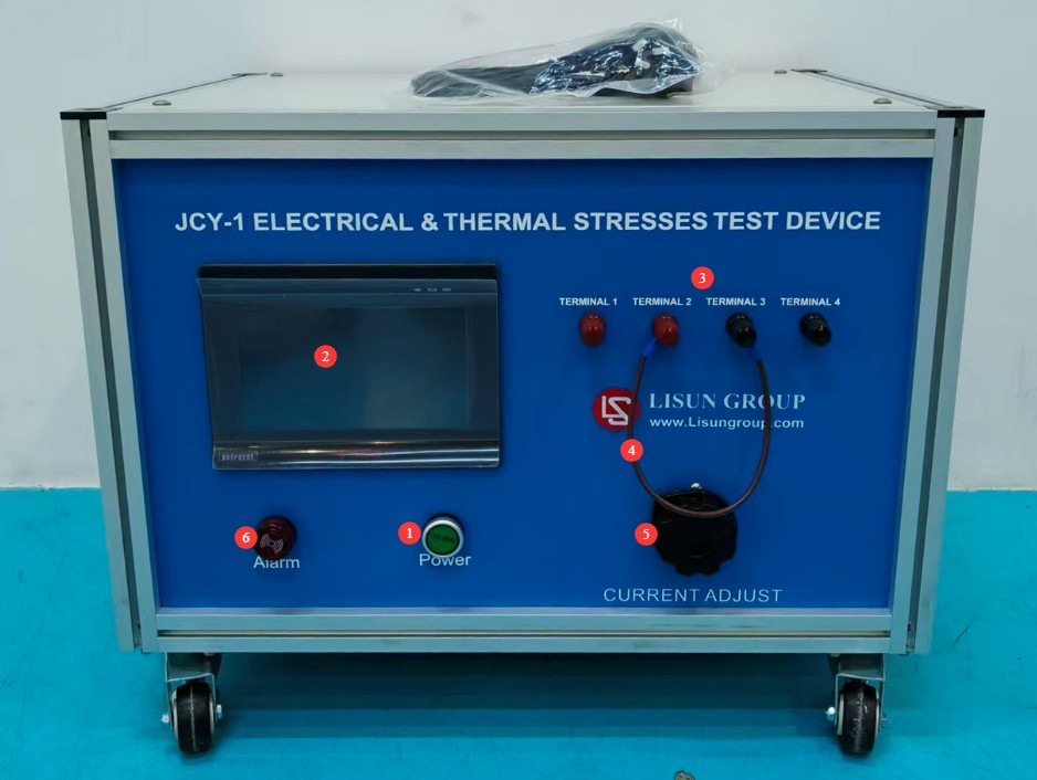
Figura 1
3.2 Panoul din spate
| Număr | notițe |
| ① | Mufă pentru cablu de alimentare |
| ② | Ventilator răcire |
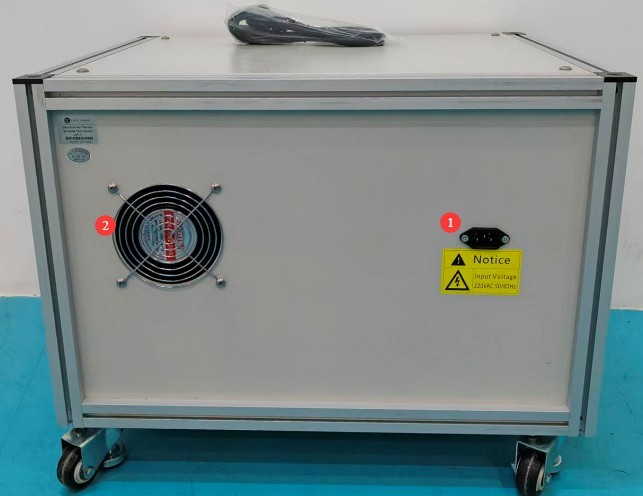
Figura 2
4. Introducere în interfața programului
4.1 Interfață de testare
| Număr | notițe |
| ① Real-time power-on time | Current Test Power-On Duration |
| ② Preset power-on time | Customize the power-on duration (in minutes/seconds) |
| ③ Real-time power-outage duration | Current Test Power Outage Duration |
| ④ Preset power-off time | Customize the power-off duration (in minutes/seconds) |
| ⑤ Number of real-time on/off cycles | Number of cycles completed |
| ⑥ Preset number of on/off cycles | Customize the total number of cycles |
| ⑦ Real-time current measurement | Current output value (in A) |
| ⑧Start/Stop | Click to start/stop the test |
| ⑨Zero | Click to reset the current test data |
| ⑩Resetează | When the device triggers an alarm, click to clear the alarm. |
| ⑪Home | Înapoi la pagina principală |
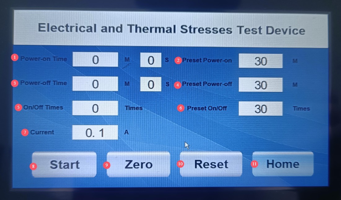
Figura 3
4.2 Help Interface
Users may refer to the recommended testing procedures and precautions.
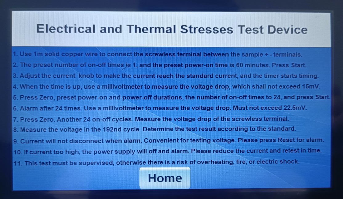
Figura 4
5. Pregătiri înainte de test
5.1 Verification of the Test Current for Test Specimen Leads
Test Specimens: 5 brand-new threaded terminals, free of damage or oxidation, rated for the same current as the socket
Select a new single-core solid copper conductor with a length of 1 m based on the rated current. Refer to the rated current of the screwless terminals to determine the test current and the conductor cross-sectional area, as shown in the table below.
| Curent nominal (A) | Test Current (A) | Wire Cross-Sectional Area (mm²) |
| ≤ 4 | 9 | 0.75 |
| > 4 și ≤6 | 13.5 | 1 |
| > 6 și ≤ 10 | 17.5 | 1.5 |
| > 10 și ≤16 | 22 | 2.5 |
5.2 Preparation of Tools and Supplies
Tools to Bring: millivoltmeter (for measuring voltage drop), insulated screwdriver, wire strippers;
Supplies: Copper wire of the appropriate specifications, jumper wires.
5.3 Specifications for Test Specimen Wiring
Connect the input wire to the red terminal and the output wire to the black terminal on the screwless terminal block;
The wire should be stripped to an appropriate length and crimped securely to ensure a good connection.
6. Procedura de testare
6.1 Electrical Stress Test (Step a)
| Procedură | notițe |
| ① | First, turn the current adjustment knob to the minimum setting, connect the test specimen, and verify that the connections are secure. |
| ② | On the touchscreen, enter the test interface and set the power-on time to 60 minutes, the power-off time to 0, and the number of power cycles to 1. |
| ③ | Click “Start” to begin the test, and turn the current knob to set the current to the standard test value. |
| ④ | Keep the power on for 1 hour; current flows only through the terminals, not through the outlet; do not move the wires or the test specimen at any time during the process. |
| ⑤ | After power-up, the device triggers an alarm, and the current continues to be output. |
| ⑥ | Immediately adjust the device’s output current from the test current at the threadless terminal to the rated current. |
| ⑦ | Use a millivoltmeter to measure the voltage drop across each threadless terminal. |
| ⑧ | Acceptance Criteria: A voltage drop of ≤15 mV is considered acceptable. |
6.2 Thermal Stress Cycling Test (Step b)
| Instrucțiuni | notițe |
| ① | After completing the electrical stress test, click “Zero” to reset the data; do not move the specimen or the wires. |
| ② | Parameter settings: Power on for 30 minutes, power off for 30 minutes, preset number of on/off cycles: 24. Click Start. |
| ③ | After completing the above 24 cycles, the device sounds an alarm, and the current remains at the output level. |
| ④ | Immediately adjust the device’s output current from the test current at the threadless terminal to the rated current. |
| ⑤ | Use a millivoltmeter to measure the voltage drop across the two ends of the threadless terminal and record the reading. |
| ⑥ | Repeat the above procedure to complete a total of 192 temperature cycles (measuring the pressure drop once every 24 on-off cycles). |
6.3 Evaluarea rezultatelor testelor
Voltage Drop Assessment: After every 24 cycles and after 192 cycles, the voltage drop must be ≤22.5 mV or ≤twice the value measured after 24 cycles (whichever is lower);
Visual Inspection: Upon visual inspection under normal lighting conditions, there are no cracks, deformations, melting, or other damage that would affect usability;
Mechanical Strength: After testing, the mechanical strength tests specified in Clause 12.3.10 of GB/T 16915.1 (IEC 60669-1) were repeated, and all test specimens met the requirements.
7. Proceduri post-test
7.1 Încheierea testului
Când testul este complet sau dacă îl opriți manual, atingeți „Resetare” pe ecranul tactil pentru a șterge mesajele de alarmă și a reseta datele testului.
7.2 Pană de curent
First, turn the current adjustment knob to the minimum setting. After the discharge is complete (wait at least 1 minute), turn off the power. Then disconnect the millivoltmeter leads and the test specimen leads.
8. Întreținerea și îngrijirea zilnică a echipamentelor
8.1 Întreținerea de rutină
Înainte de a porni echipamentul, verificați dacă exteriorul este curat și nu prezintă deteriorări;
After the test is complete, wipe down the surface of the equipment and the test area of the specimen with an antistatic, dry cloth;
Check the equipment terminals for oxidation or burn marks; if any are found, wipe them with a specialized contact cleaner and replace the terminals if necessary;
Inspect jumper wires regularly; if they show no signs of overheating, aging, or damage, replace them promptly;
Check to see if the internal cooling fan is operating normally. If you hear unusual noises or if the fan is not running, please contact us immediately for repair.
8.2 Depozitare pe termen lung
Dacă dispozitivul nu va fi utilizat pentru o perioadă lungă de timp, depozitați-l într-un loc uscat, bine ventilat, ferit de umiditate și de lumina directă a soarelui;
Deconectați toate cablurile, depozitați accesoriile separat și acoperiți dispozitivul cu o cârpă impermeabilă;
Turn the device on for 30 minutes each month to prevent the internal electronic components from deteriorating.
9. Depanarea și rezolvarea problemelor comune
| Simptome de eroare | Cauze posibile | Procedură |
| The output current cannot be adjusted after the test is started. | Screwless terminals and wires are not properly connected | Please stop the test, check and confirm that the wiring is correct and secure, and then retest. The output current cannot be adjusted if the circuit is open. |
| A red message appears on the screen: “Excessive current!” accompanied by an alarm. | Overcurrent alarm; protection triggered due to excessive current | Immediately reduce the current and restart the test. |
| Touchscreen Lag | Defecțiune a sursei de alimentare, blocare sistem | Verificați sursa de alimentare pentru a vă asigura că îndeplinește cerințele; reporniți dispozitivul și încercați din nou. |