
 Engleză
 中文简体
中文简体 Русский
 Español
 Português
 Türkçe
 العربية
 Deutsch
 Polski
 Italiano
 Français
 한국어
한국어 ไทย
ไทย Tiếng Việt
 日本語
日本語





























Simulator de variație a tensiunii bipolare în patru cadrane
Manual de utilizare
Aplicabil LISUN models: LIS-APS-40100K300、LIS-APS-4010K300、LIS-APS-40150K300、LIS-APS-40200K300、LIS-APS-4020K300、LIS-APS-40300K300、LIS-APS-4030K300、LIS-APS-4050K300、LIS-APS-4070K300、LIS-APS-80100K300、LIS-APS-8010K300、LIS-APS-80150K300、LIS-APS-80200K300、LIS-APS-8020K300、LIS-APS-80300K300、LIS-APS-8030K300、LIS-APS-8050K300、LIS-APS-8070K300
1. Noțiuni de bază despre echipament
1.1 Clasificarea modelului
| LISUN Model | LIS-APS-4010K300 | LIS-APS-4030K300 | LIS-APS-8050K300 | LIS-APS-80100K300 |
|---|---|---|---|---|
| Caracteristici de ieșire | Four-Quadrant Bipolar | |||
| Rated Output Voltage Un | ±40 V DC/AC | ±80 V DC/AC | ||
| Rated Output Current In | 0 to ±10 A | 0 to ±30 A | 0 to ±50 A | 0 to ±100 A |
| Transient peak current Ip | 2 times the rated current, duration 20–200 ms | |||
| Frequency Range (Sine Wave) | DC–300 kHz (output error < 0.1%) | |||
| Modul de ieșire | Constant voltage, constant current. (Output accuracy: 0.05%; Setting accuracy: 1 mV/1 mA) | |||
| Rata de creștere a tensiunii | ≥15 V/µs | |||
| Amplitudinea tensiunii AC | >30 Vpp @ 100 kHz; >10 Vpp @ 300 kHz | |||
| Capacitate de incarcare | At full AC load, Vpp drops by <200 mV | |||
| Metoda de ieșire a frecvenței | Fixed, Linear, Logarithmic | |||
| Impedanta sursă | Adjustable from 0 mΩ to 500 mΩ (resolution: 1 mΩ, accuracy: <±5%). Also supports external resistance to meet specific automotive manufacturer standards. | |||
| Ripple de tensiune | <10 mVrms (ripple and noise: <30 mVpp) | |||
| Editare combinată a formelor de undă | ISO 7637-2 P2b and P4 / Linear / DC / Sine wave / Square wave / Triangle wave / Exponential wave / Arbitrary waveform; supports frequency sweeping | |||
| Number of Editable Steps for Combined Waves | Până la 500 pași | |||
| Minimum editable time for composite waves | 5 μs | |||
| Count the points on an arbitrary waveform | ≤ 16000,000 | |||
| Editable point spacing for arbitrary waves | 0.1 µs–1 s | |||
| Format de undă arbitrară | Excel, CSV | |||
| Caracteristici de protecție | Features overcurrent, overvoltage, short-circuit, and overtemperature protecţie | |||
| Sistem de control | 10.1-inch Chinese-English Android Capacitive Touchscreen Display + Supports Remote Control via PC Software | |||
| Analiza eșantionării FFT Ripple | The built-in oscilloscope displays the output waveform in real time. | |||
| Eșantionare în buclă închisă prin suprapunere de ondulații | Equipped with built-in ripple voltage and current probes, it enables direct closed-loop ripple testing at a distance of 10 cm in accordance with ISO 16750-2:2023, Figure 5. | |||
1.2 Standarde aplicabile
| Numărul standard | Titlu standard |
|---|---|
| GB / T 28046.2-2019 | Condiții de mediu și teste pentru echipamente electrice și electronice în vehicule rutiere - Partea 2: Sarcini electrice |
| GB / T 21437.2-2021 | Test Methods for Electromagnetic Disturbances Caused by Conduction and Coupling in Electrical and Electronic Components of Road Vehicles—Part 2: Conducted Transient Emissions and Immunity Along Power Lines |
| SMTC 38000001-2012 | General Testing Requirements for Automotive Electronic and Electrical Components |
| ISO 16750-2: 2023 | Vehicule rutiere — Condiții de mediu și testare pentru echipamente electrice și electronice — Partea 2: Sarcini electrice |
| ISO 7637-2:2021 | Road Vehicles—Electrical Disturbances from Conduction and Coupling—Part 2: Electrical Transients Conducted Solely Along Power Supply Lines |
| LV 124 | Electrical and Electronic Components in Motor Vehicles Weighing Up to 3.5 Metric Tons—Requirements, Test Conditions, and Tests for the 12-Volt On-Board Electrical System |
| LV 148-E09 | Componente electrice și electronice în autovehicule - Cerințe și condiții de testare pentru sistemul electric de bord de 48 V |
| VW 80000:2023 | Geometric Tolerance and Quality Control Specifications for Automotive Components |
| GS 95024-2:2011 | Electrical and Electronic Components in Motor Vehicles—Supplementary Requirements and Tests for 12V On-Board Electrical System Components |
| GMW 3172:2023 | General Specifications for Electrical and Electronic Components – Environmental and Durability |
1.3 Scenarii de aplicație
The LIS-APS Series Four-Quadrant Bipolar Voltage Variation Simulator is a high-precision power supply simulation device that supports bidirectional energy flow. Based on a fully controlled H-bridge topology, it enables disturbance-free transitions across all four operating quadrants and provides seamless switching between positive and negative voltage and current outputs.accurately simulating dynamic voltage changes, transient pulses, polarity reversals, and operating conditions such as open circuits, short circuits, and wire disconnections. It also features customizable waveform editing, adjustable impedance, and wide-frequency ripple superposition, making it a core piece of equipment for power supply adaptability testing in fields such as automotive electronics and rail transit.
Applications: In the automotive electronics sector, it simulates operating conditions such as fluctuations in vehicle battery voltage, start-stop cycles, and open circuits or short circuits in wiring harnesses to verify the immunity and reliability of components such as ECUs, BMSs, and vehicle lights; in the rail transit and aerospace sectors, it performs power supply adaptability testing on onboard electronic equipment; in industrial control and medical electronics, to verify the operational stability of equipment under power supply fluctuations; and in energy storage and motor applications, to simulate voltage and current characteristics during energy regeneration.
2. Precauții pentru utilizare
2.1 Cerințe de mediu
Temperatura ambiantă: 23 °C ± 5 °C; umiditate relativă: 45–75%, fără condens; altitudine: ≤2000 m; fără vibrații puternice sau interferențe electromagnetice în zona înconjurătoare; utilizarea echipamentului în medii cu praf, inflamabile sau explozive este strict interzisă.
2.2 Cerințe de alimentare
Input power supply: AC 220 V ±10%, 50 Hz; Input power: ≤1 kW; The power supply must be reliably grounded, with a grounding resistance of ≤4 Ω; It is recommended to use a voltage-regulated power supply to prevent power grid fluctuations from affecting test accuracy.
2.3 Principii de cablare
Use power cables with the specified wire gauge to prevent the conductors from overheating under high current conditions; keep test cables as short as possible and route them in parallel to minimize the impact of parasitic parameters; ensure that the DUT (Device Under Test) enclosure is reliably connected to the equipment’s protective ground; and route signal cables separately from power cables to avoid cross-interference.
2.4 Liniile directoare privind siguranța operațională
Purtați echipament de protecție izolat; înainte de testare, asigurați-vă că toate conexiunile sunt sigure și că nu există conductori expuși; nu conectați sau deconectați cablurile de testare în timpul testării pentru a evita arsurile cu arc electric; nu atingeți dispozitivul testat sau dispozitivele de testare în timp ce se emite impulsul; dacă auziți zgomote neobișnuite, simțiți un miros neobișnuit sau vedeți fum, deconectați imediat alimentarea cu energie electrică; În timpul testării continue prelungite, asigurați-vă că echipamentul este ventilat corespunzător pentru disiparea căldurii.
3. Prezentare generală a echipamentului și cablare
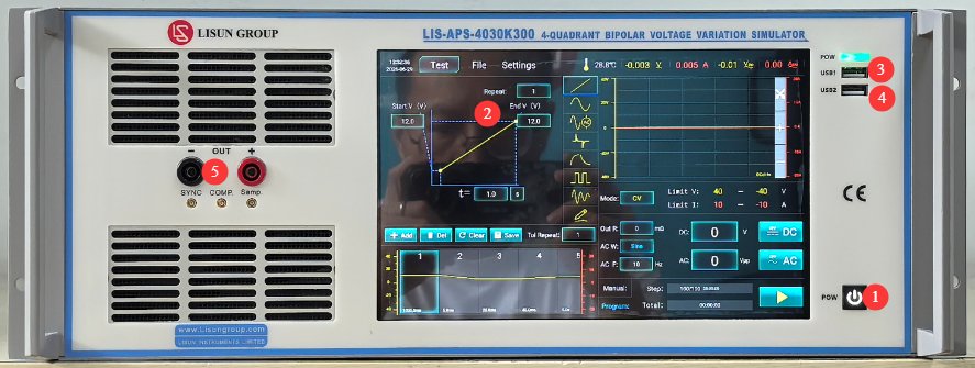
3.1 Panoul frontal
Vezi Figura 3-1.
| Număr | notițe |
|---|---|
| ① | Comutatorul de alimentare al dispozitivului: Apăsați scurt pentru a porni; apăsați și țineți apăsat pentru a opri. |
| ② | Ecran tactil capacitiv de 10.1 inci |
| ③ | Port USB1: Utilizat de LISUN ingineri pentru depanarea dispozitivelor; utilizatorii nu trebuie să îl folosească. |
| ④ | Port USB 2.0, care poate fi utilizat pentru conectarea unui mouse pentru controlul ecranului tactil sau pentru conectarea unei unități flash USB pentru actualizarea software-ului sau a fișierelor bazei de date |
| ⑤ | Output connector; observe polarity. Used to connect directly to the DUT for testing. |
3.2 Panoul din spate
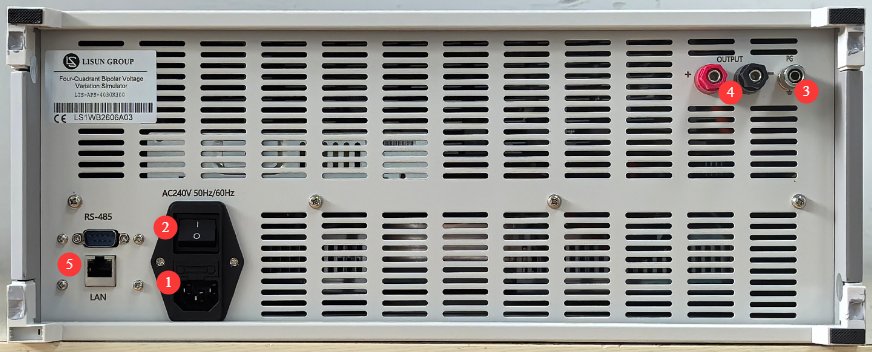
Vezi Figura 3-2.
| Număr | notițe |
|---|---|
| ① | Priză și siguranță pentru cablul de alimentare; asigurați-vă că sursa de alimentare este împământată corespunzător |
| ② | Întrerupător de circuit, întrerupător principal de alimentare cu energie electrică pentru echipament |
| ③ | Terminal de împământare de protecție: Dacă sursa de alimentare de intrare nu are o conexiune fiabilă la masă, acest terminal trebuie conectat separat la masă. |
| ④ | Output jack—pay attention to polarity; this jack functions identically to the front-panel output jack. When using it as a power source, connect it to other devices using a cable. |
| ⑤ | RS485 interface/LAN port, which can be connected to a computer to use the host software (as a backup). The host software offers the same functionality as the touchscreen; please contact us if needed. |
3.3 Introducere în Accesorii
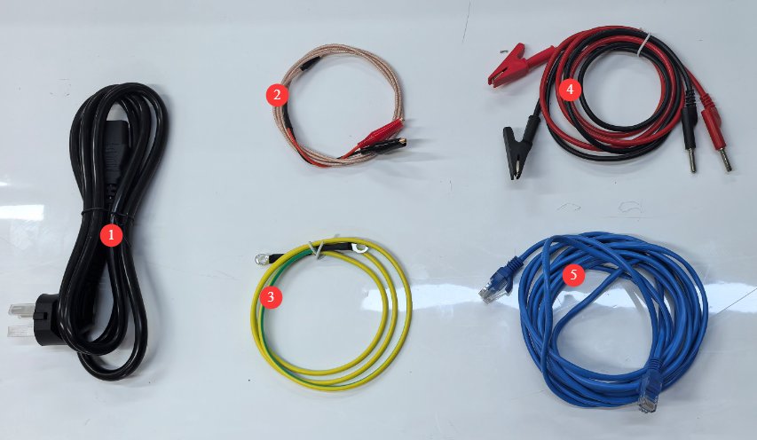
Vezi Figura 3-3.
| Număr | notițe |
|---|---|
| ① | Cablu de alimentare |
| ② | AC Output Voltage Calibration Cable, Spare. When outputting high-frequency AC voltage, if you observe that the output voltage attenuates over time, use this cable to calibrate the voltage. Please contact us if you need to use it. |
| ③ | Sârmă la sol |
| ④ | Test lead, used to connect the output port on the device’s front panel to the DUT |
| ⑤ | Cablu Ethernet, utilizat pentru conectarea unui computer la software-ul gazdă |
4. Introducere în programul cu ecran tactil
4.1 Interfață de testare
4.1.1 Use as a Power Source
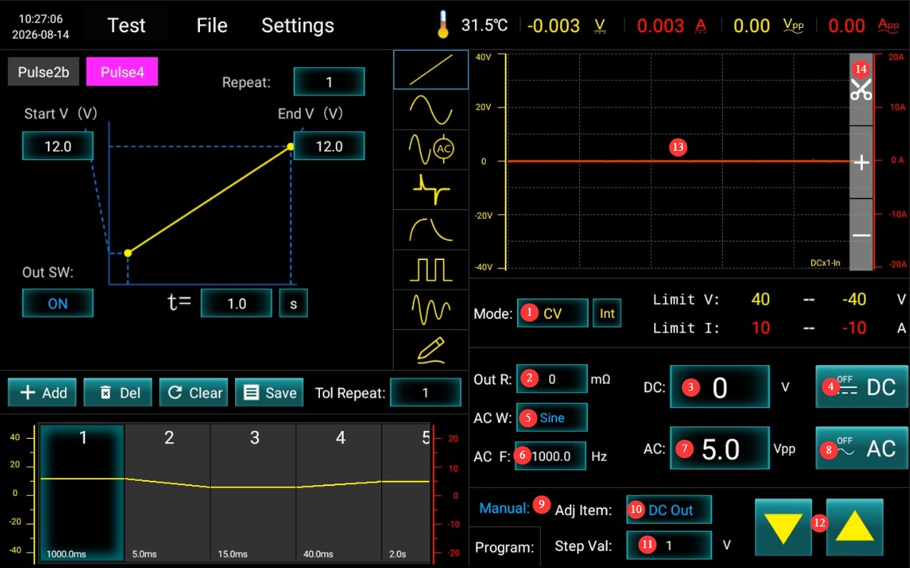
Vezi Figura 4-1.
| Număr | notițe |
|---|---|
| ① | Set the output mode for DC: CV for constant voltage, CC for constant current |
| ② | Set the Output Resistance |
| ③ | Set DC Output Voltage/Current |
| ④ | Click to turn the DC power output on or off; it can be used as a standalone output or combined with AC output. |
| ⑤ | Select an AC Waveform |
| ⑥ | Set the AC Frequency |
| ⑦ | Set the AC voltage; note that this is the Vpp value. |
| ⑧ | Click to turn the AC power output on or off; it can be output independently or combined with DC output. |
| ⑨ | Switch to Manual Adjustment |
| ⑩ | Select the regulated power supply: AC or DC |
| ⑪ | Set the step value |
| 10 | Click the up/down buttons to manually adjust the output according to the set increment value. |
| 10 | Display the current output waveform |
| 10 | Screenshot: Click to save a screenshot of the current output waveform to your device. |
4.1.2 Standard Operational Testing
Vezi Figura 4-2.
| Număr | notițe |
|---|---|
| ① | Here are the shortcut keys for the Pulse 2b and Pulse 4 waveforms in 12V mode. Simply click to select them—no need to adjust any parameters. |
| ② | If you need to use the Pulse 2b and Pulse 4 waveforms in 24V mode or conduct tests according to other standard specifications, you must access the database file interface to make your selection. Once selected, no parameters need to be modified. |
| ③ | Switch to Programming Mode |
| ④ | Click to run the test |
| ⑤ | Display the steps and duration of the current test |
| ⑥ | Display the current output waveform |
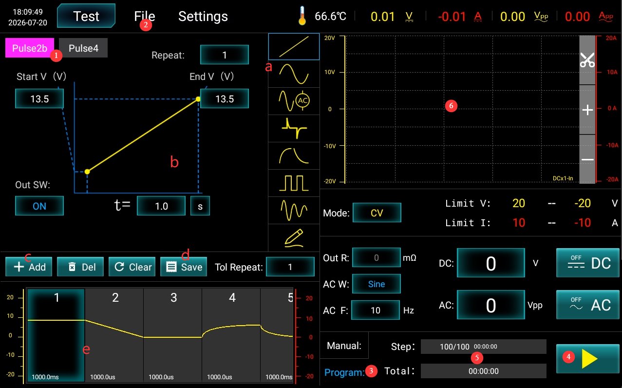
If you need to perform custom tests, refer to the table below.
| Număr | notițe |
|---|---|
| a | Waveform selection, from top to bottom: DC linear wave, AC sine wave/triangular wave/TMW pulse wave, AC test mode (constant voltage), AC closed-loop test/constant current, AC open-loop test mode, differential wave, exponential wave, square wave, decay wave, custom waveform (reserved; please contact us if you need to use this option) |
| b | Waveform Diagram and Parameter Settings |
| c | After selecting a waveform and configuring the parameters, click “Add.” |
| d | Once all settings are configured, click “Save” to save the current test parameters to the database file. |
| e | All waveforms added in sequence |
4.2 Interfața fișierelor bazei de date
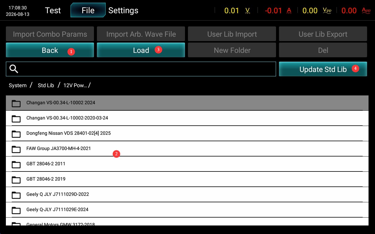
Vezi Figura 4-3.
| Număr | notițe |
|---|---|
| ① | Back to the Previous Directory |
| ② | Select the standard file you want to test |
| ③ | Double-click or click “Import” to open the test interface and run the test. |
| ④ | If you have other standard tests but do not wish to create custom tests, please contact us and send us the details of the corresponding standard. We will guide you on how to use a USB drive to update the database file directly with that standard. |
4.3 Interfață de setări
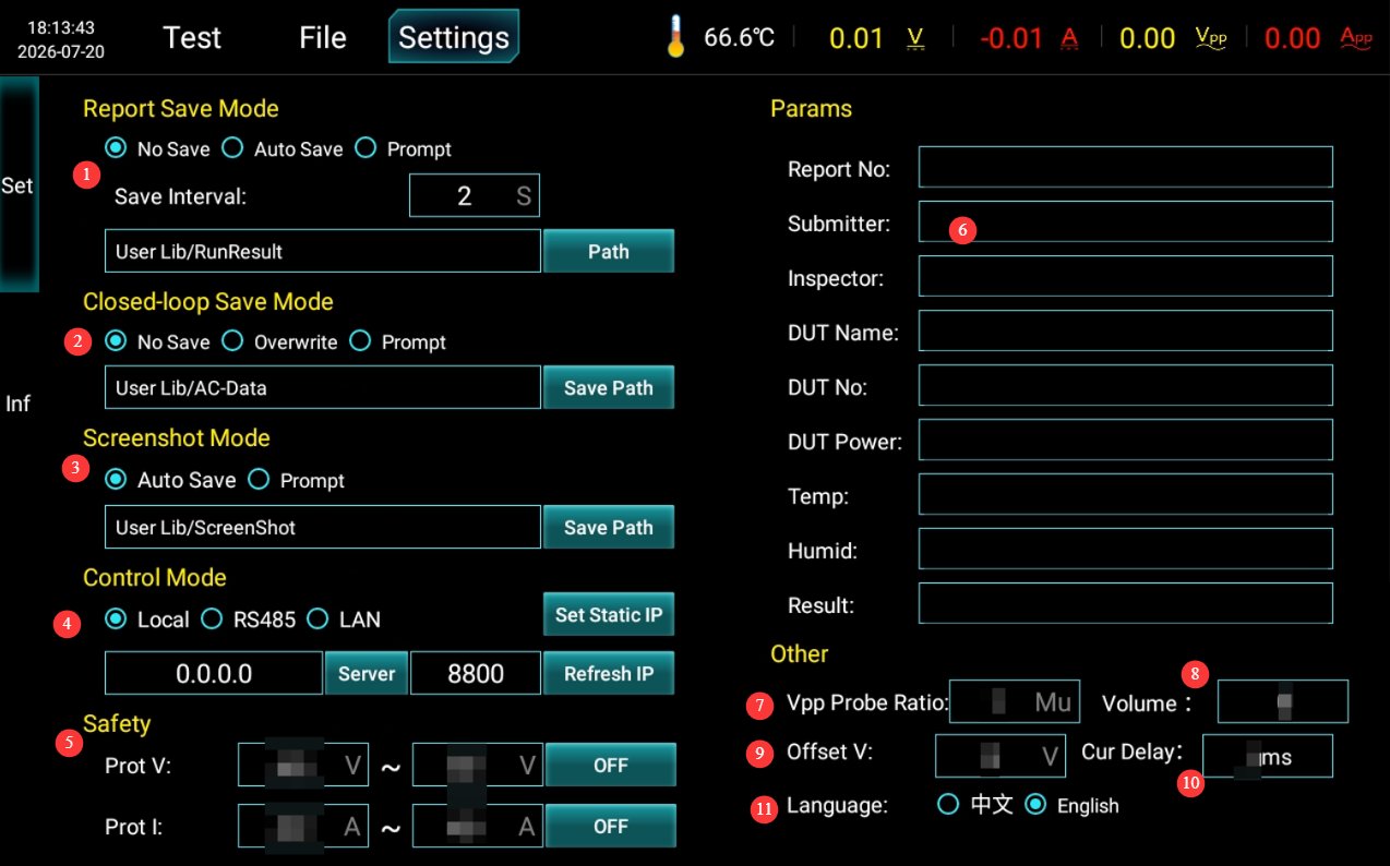
Vezi Figura 4-4.
| Număr | notițe |
|---|---|
| ① | Report Storage Methods and Paths |
| ② | Closed-Loop Test Save Options and Save Paths |
| ③ | How to Save Screenshots and Where They Are Saved |
| ④ | Communication settings are set to LOCAL by default. If you need to use host computer software, you can switch to RS485 or the LAN port. Please contact us. |
| ⑤ | Security settings: Use the factory default settings; do not change them. |
| ⑥ | Test Report Parameter Settings |
| ⑦ | Probe Multiplier: This setting is only effective during AC closed-loop testing. The value set for Vpp is multiplied by this multiplier. Use the factory default setting; do not modify it. |
| ⑧ | Setări volum |
| ⑨ | Combined Wave Compensation Voltage: If a compensation voltage is set here when outputting a combined waveform on the test interface, this value will be added. Use the factory default setting; do not modify it. |
| ⑩ | For overcurrent delay, use the factory default setting; do not modify it. |
| ⑪ | Schimbați limba de afișare |
Note: We do not recommend enabling the auto-save feature. Automatically saving large numbers of waveform and report files over time will consume device storage space and may cause the touchscreen program to run slowly.
5. Proceduri de testare
5.1 Using It as a Power Source
Ensure that all devices are powered off; use a test cable to connect the device’s output port to the DUT’s power input port; after setting the desired power output parameters as described in Section 4.1.1, start the output; when finished, click “Disconnect Output” again.
5.2 Standard Operational Testing
5.2.1 Cablare
Ensure that both the device and the DUT are powered off; use a test cable to connect the device’s output port to the DUT’s power cord.
5.2.2 Testarea funcțională
First, refer to Section 4.1.1 to set the appropriate power supply parameters for the DUT and enable the power supply output, ensuring that the DUT is in normal operating condition.
Then, refer to Section 4.1.2 to select the required test standard or configure the test parameters, and run the test; observe the DUT’s operating status and record any observations; wait for the test to complete—or, in case of an emergency, press the stop button to halt the test immediately.
5.2.3 Evaluarea rezultatelor
| Nivelul funcțional | Definiția standardelor | Judging Guidelines |
|---|---|---|
| Nota A | During and after the application of interference, all functions of the DUT operated normally as designed, and performance parameters remained within specifications. | No functional abnormalities were observed throughout the entire process, and no intervention was required after testing—this meets the highest standards. |
| Grad B | During the application of interference, all functions remain operational, but certain parameters may exceed their tolerance limits; once the interference is removed, all functions automatically return to their normal ranges, and the storage function maintains Class A performance. | Parameter drift and minor performance degradation are permitted during testing, but no functional failures may occur; the system must automatically recover after testing. |
| Grad C | During the application of interference, one or more functions do not operate as designed; once the interference is removed, the functions automatically return to normal. | During testing, phenomena such as functional interruptions and logical anomalies are permitted; after testing, the system should recover automatically without the need for manual intervention. |
| Gradul D | Malfunction occurs while interference is present; after the interference is removed, normal operation can be restored only through simple manual steps (power cycle, reset). | Freezing, rebooting, and similar issues are acceptable, but there must be no hardware damage, and the system must be able to recover with a simple reset. |
| Clasa E | During and after the interference, the function will be permanently disabled and cannot be restored without repairing or replacing the hardware. | Permanent damage; automatically deemed a failure |
Core Principle: If the DUT exhibits a Grade E performance (hardware damage, permanent loss of functionality), the test is deemed a failure regardless of the agreed-upon grade; for Grades A through D, pass/fail is determined based on the minimum acceptable grade agreed upon by the supplier and the customer.
5.2.4 Proceduri post-testare
Ensure that both the equipment and the DUT are powered off; disconnect the wiring on the DUT side first, then disconnect the wiring on the equipment side.
6. Întreținerea și îngrijirea zilnică a echipamentelor
6.1 Curățenie zilnică
6.1.1 Programul și procedurile de curățare
După fiecare utilizareCurățați suprafața ecranului tactil și îndepărtați praful de pe panoul dispozitivului;
Săptămânal Curățați carcasa echipamentului și filtrele din orificiile de ventilație;
LunarCurățați praful din interiorul echipamentului (trebuie efectuată de un profesionist).
6.1.2 Metode de curățare
Wipe the exterior with a clean, soft, lint-free cloth; use a dedicated screen cleaner for the touchscreen; clean the vents with a soft-bristled brush and use a vacuum cleaner if necessary; do not use corrosive solvents such as acetone.
6.2 Inspecții periodice
Verificați cablul de alimentare pentru a depista eventualele deteriorări sau uzură; verificați dacă conexiunea la masă este fixată; verificați dacă ventilatorul funcționează normal; verificați dacă butoanele și ecranul tactil răspund; verificați blocurile de conexiuni pentru oxidare sau conexiuni slăbite.
6.3 Depozitare și manipulare
6.3.1 Cerințe pentru depozitarea pe termen lung
Storage Conditions: Temperature -10°C to +50°C, humidity ≤ 85%; Clean the equipment and apply dust protection before storage; Power it on once every 3 months, running it for at least 30 minutes each time; Avoid stacking or applying heavy pressure to prevent the panel from warping.
6.3.2 Precauții la manipulare
Unplug all external cables before moving the device; use the original packaging and ensure it is properly cushioned and protected; keep the device upright during transport and avoid harsh vibrations; when lifting, grip the bottom and sides of the device—do not lift by the panel.
6.4 Cerințe privind intervalul de calibrare
Pentru a asigura acuratețea măsurătorilor și fiabilitatea operațională a echipamentului, se recomandă trimiterea periodică a acestuia la un laborator de metrologie terț calificat pentru calibrare. Intervalul de calibrare recomandat este de 12 luni. Utilizatorii pot determina intervalul specific de calibrare în funcție de frecvența de utilizare, condițiile de mediu și cerințele sistemului de calitate.
7. Depanarea și rezolvarea problemelor comune
| Simptome de eroare | Cauze posibile | Procedură |
|---|---|---|
| Dispozitivul nu se va porni | The input power supply main power switch on the back is not turned on, or the fuse has blown | Turn on the input power supply switch located at the power cord receptacle on the back of the unit; check the fuse, and if it has blown, replace it with a fuse of the same rating. |
| Defecțiune a ecranului tactil după pornire | Blocarea sistemului, cablu panglică slăbit | Dacă problema persistă după repornire, deconectați alimentarea, scoateți carcasa exterioară a dispozitivului și verificați dacă cablul panglică al ecranului tactil este slăbit. |
| Testul s-a oprit automat la jumătatea drumului | Over-temperature protection triggered, overcurrent/overvoltage protection triggered | Verificați dacă ventilația echipamentului este obstrucționată și dacă temperatura ambiantă este prea ridicată; verificați dacă există scurtcircuite sau supraîncărcări la dispozitivul testat. |
| Unitate flash USB nerecunoscută | USB drive format is incompatible or has excessive capacity | Folosește o unitate USB formatată în FAT32 cu o capacitate de maximum 32 GB; dacă aceasta nu funcționează, încearcă o altă unitate USB. |
| Fără tensiune/curent după activarea ieșirii | Anomalie de cablare DUT, funcție de protecție declanșată | După deconectarea ieșirii, verificați dacă dispozitivul testat este cablat corect și că nu există circuite deschise sau scurtcircuite; verificați dacă există avertismente de supratensiune, supracurent sau supratemperatură și încercați din nou după rezolvarea problemei. |
| Precizie anormală a tensiunii/curentului de ieșire | Setări incorecte ale rezistenței de ieșire; lipsă de calibrare pe termen lung | Verificați dacă parametrii impedanței sursei îndeplinesc cerințele de testare; contactați o organizație terță de metrologie pentru a efectua calibrarea. |