
 Engleză
 中文简体
中文简体 Русский
 Español
 Português
 Türkçe
 العربية
 Deutsch
 Polski
 Italiano
 Français
 한국어
한국어 ไทย
ไทย Tiếng Việt
 日本語
日本語





























Tester de curent de scurgere a condensatorului
Manual de utilizare
Aplicabil LISUN modele: LS6586-500,LS6586-800
1. Noțiuni de bază despre echipament
1.1 Prezentare generală a echipamentelor
1.1.1 Clasificarea modelului
| Specificații/Numere de model | LS6586-500 | LS6586-800 |
|---|---|---|
| Tensiunea de testare | 1–500 V (continuously adjustable) | 1–800 V (continuously adjustable) |
| Funcții de testare | LC (Leakage Current), IR (Insulation Resistance) | |
| Precizia tensiunii | 0.5% of the setpoint ±0.2 V | |
| Raza de masurare | LC (0.001 μA–20.00 mA), IR (0.01 kΩ–99.99 G) | |
| Precizia măsurării | 1% ± 0.05 μA | |
| Timpul de încărcare | 0–999 s (continuously adjustable) | |
| Timpul testului | Fast: About 30 times per second; Medium: About 15 times per second; Slow: About 6 times per second | |
| Interval de testare | Auto, 20 mA, 2 mA, 200 µA, 20 µA, and 2 µA—a total of 5 ranges | |
| Rezultatele testului | Pass, Fail, Above Limit, Below Limit; buzzer alarm; indicator light display | |
| interfaţă | RS232C, USB Device, Handler, GPIB (optional) | |
| Volum | 310 × 110 × 315 mm | |
| Greutate Netă | 8 kg | |
1.1.2 Aplicații tipice
This equipment is capable of performing leakage current and insulation resistance tests on capacitors. It is suitable for applications such as factory-level testing of electronic components, incoming material inspection, R& D sample verification, automated sorting on production lines, and post-sales failure analysis. It supports a wide range of capacitors, including aluminum electrolytic capacitors, ceramic capacitors, film capacitors, and tantalum capacitors.
1.2 Equipment Configuration Verification
1.2.1 Despachetarea
Când despachetați dispozitivul, manipulați-l cu grijă pentru a evita zgârierea carcasei exterioare cu unelte ascuțite. După despachetare, inspectați mai întâi exteriorul dispozitivului pentru a vă asigura că nu există deformări sau lovituri vizibile și că butoanele nu sunt deteriorate sau slăbite. Dacă observați anomalii la dispozitiv sau la accesoriile sale, do not turn it on. Please contact us immediately.
1.2.2 Unitatea principală și accesoriile
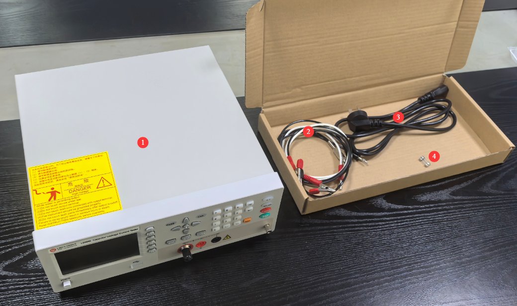
Vezi Figura 1-1.
| Număr | notițe |
|---|---|
| ① | LS6586 Tester de curent de scurgere a condensatorului de serie |
| ② | Cabluri de testare |
| ③ | Cablu de alimentare |
| ④ | Siguranțe de rezervă |
1.2.3 Descărcarea documentelor electronice
Linkurile către manualul de utilizare digital, cardul de garanție, certificatul de calibrare și alte documente au fost trimise prin e-mail. Dacă nu ați primit e-mailul, vă rugăm să ne contactați pentru a obține din nou linkurile.
2. Măsuri de siguranță
2.1 Siguranță electrică și împământare
This device is a Class I safety instrument and must be powered using a three-prong outlet with a protective ground, with a protective ground resistance of ≤4 Ω. Under no circumstances should the protective ground wire be disconnected or removed; otherwise, there is a risk of induced voltage on the device housing, which may result in electric shock.
The supply voltage must match the device settings: It supports AC 100–120 V or 198–242 V, with a frequency of 46–64 Hz; the power supply must be ≥85 VA. The input voltage range can be adjusted using the voltage selector switch on the rear panel of the device.
Before replacing a fuse, you must first unplug the power cord. Use a fuse that matches the manufacturer’s specifications; do not substitute it with copper wire or a fuse of an incorrect rating.
2.2 High-Voltage Operational Safety
The test terminals of the equipment output high voltage, up to 500 V or 800 V. Never touch the test terminals, the metal parts of the test clamps, or any live parts of the device under test with your bare hands to prevent electric shock.
Before inserting or removing the device under test, you must first press the [Discharge] button on the front panel. Only proceed once you have confirmed that the equipment is in a discharged state and the high-voltage indicator light is off. It is strictly prohibited to insert or remove the device under test while it is energized during the test.
After the equipment is turned off, dangerous voltages may still remain in the internal capacitors. If you need to disassemble the unit, replace a fuse, or perform maintenance, you must disconnect the power and wait at least 40 minutes to allow the internal capacitors to discharge completely before proceeding. This work must be performed by qualified personnel.
Do not connect external voltage or current sources to the test or monitoring terminals; if an external bias source is required, reliable electrical isolation measures must be implemented.
2.3 Environmental Safety Requirements
Do not use the equipment in environments containing flammable or explosive gases, highly corrosive gases, dust levels exceeding the permissible limit, or strong electromagnetic interference.
Test environment to ensure accuracy: Temperature 0°C to 40°C, relative humidity ≤75% RH, no condensation; the recommended calibration-grade test environment is 23±5°C, with relative humidity ≤65% RH.
There are ventilation openings on both sides of the device. Do not block them during use; ensure proper ventilation to prevent internal overheating, which could affect accuracy or damage components.
Test leads should be kept away from strong electromagnetic fields to prevent interference with measurement results.
2.4 Altele
Pentru aspectele care nu sunt acoperite de acest manual, vă rugăm să procedați cu prudență sau să ne contactați.
3. Prezentare generală a echipamentului și cablare
3.1 Introducere în panoul frontal
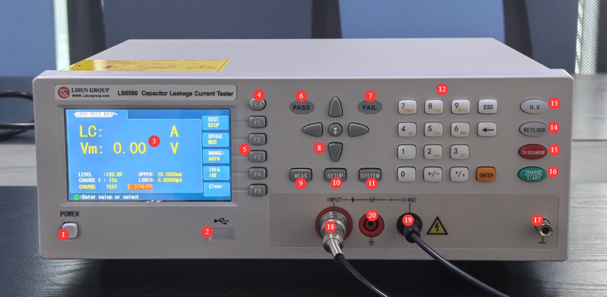
Vezi Figura 3-1.
| Număr | notițe |
|---|---|
| ① | Întrerupător |
| ② | USB port, used for upgrading the operating system |
| ③ | LCD color display; the measurement screen appears by default when the device is turned on. |
| ④ | File button: Opens the file management interface, where you can save, delete, or copy parameter settings. |
| ⑤ | F1–F5 soft keys; their functions vary depending on the current screen and correspond to the function labels on the left side of the screen; used to select menus and adjust settings |
| ⑥ | PASS: Lights up when the test results are satisfactory |
| ⑦ | FAIL—Lights up when test results are unsatisfactory |
| ⑧ | Arrow keys: Move the cursor up, down, left, and right |
| ⑨ | Measurement button: Return to the measurement screen with a single tap |
| ⑩ | Settings button: Return to the Settings screen with a single tap |
| ⑪ | System Button: Return to the system settings screen with a single click |
| 10 | Numeric Keypad Area |
| 10 | High-voltage indicator light: Remains lit when high voltage is present at the test terminals, warning of high-voltage hazards. |
| 10 | Lock button: Locks/unlocks the panel buttons to prevent accidental operation |
| ⑮ | Discharge Button: Pressing this button at any time immediately puts the device into discharge mode, disconnecting the test object from the internal high-voltage circuit. |
| ⑯ | Charge/Start button: In single-step test mode, press to start a measurement; in automatic test mode, press to start the test sequence |
| ⑰ | If the ground wire of the power cord is not properly connected to the chassis ground terminal, you can ground the chassis separately. |
| 11 | INPUT terminal (+), current sampling terminal; connect to the positive terminal of the device under test |
| ⑲ | HV Terminal (-), negative high-voltage output terminal; connect to the negative terminal of the device under test |
| ⑳ | Precharge interface, used to precharge the capacitor under test; requires a special fixture for operation |
Note: Never reverse the polarity of the capacitor! Connect the positive terminal to INPUT (+) and the negative terminal to HV (-). Reversing the polarity will cause the capacitor to break down and damage the instrument’s internal circuitry!
3.2 Introduction to the Back Panel
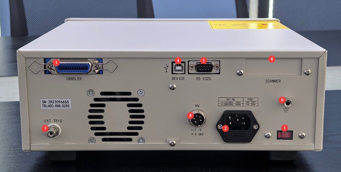
Vezi Figura 3-2.
| Număr | notițe | |
|---|---|---|
| ① | Input voltage switch; the default setting at the factory is 230V. | |
| ② | Power Outlets and Fuses | |
| ③ | HANDLER interface, 24-pin connector, connects to automated sorting equipment, transmits test result signals, and receives external trigger signals | |
| ④ | Port USB | If you need to connect to computer software to control the device, custom software is required. |
| ⑤ | RS-232 Interface | |
| ⑥ | SCANNER interface, a reserved expansion interface that allows connection of multiple scan modules | |
| ⑦ | External Trigger Interface: Connects to external trigger devices (such as foot switches, PLC signals, etc.) to enable externally triggered testing. | |
| ⑧ | High-voltage output port; can be connected to an aviation connector to output high voltage for testing; functions identically to the front panel INPUT terminal (+) and HV terminal (-) | |
| ⑨ | Chassis ground terminal; functions the same as the front panel chassis ground terminal | |
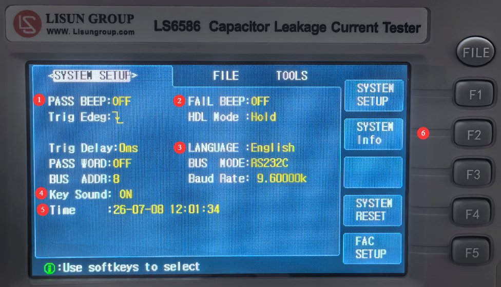
4. Introducere în interfața programului
4.1 Measurement Interface (using the LC as an example)
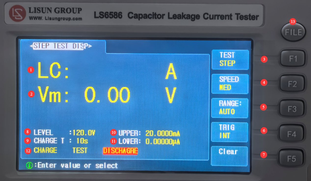
Vezi Figura 4-1.
| Număr | notițe | |
|---|---|---|
| ① | Leakage Current Display | |
| ② | Afișajul tensiunii de ieșire | |
| ③ | Set the test mode to STEP (step-by-step) or AUTO (automatic) | |
| ④ | Set the test speed, including FAST (30 times per second), MED (15 times per second; recommended for everyday use), and SLOW (6 times per second) | |
| ⑤ | Range Setting: We recommend using the “Auto” setting, which allows the device to automatically select the optimal range. | |
| ⑥ | Mod de declanșare | Internal Trigger (INT): The device automatically and continuously performs charge–test–discharge cycles, making it suitable for manual, individual testing. |
| External Trigger (EXT): Requires a single measurement to be triggered via a foot switch, PLC signal, or HANDLER interface; suitable for assembly lines and automated workstations | ||
| ⑦ | Zeroing: Zeroing must be performed when using the device for the first time, replacing test leads, experiencing significant changes in ambient temperature or humidity, after prolonged periods of non-use, or when test values show abnormal deviations, in order to eliminate the effects of parasitic leakage current in the test leads and circuit. During the zeroing operation, the test leads are in a completely open-circuit state and are not connected to any device under test. | |
| ⑧ | Test Voltage Settings: Use the arrow keys to move the cursor and configure the settings. | |
| ⑨ | Charging Duration Settings: Use the arrow keys to move the cursor and configure the settings. | |
| ⑩ | To set the maximum leakage current value, use the arrow keys to move the cursor and make the setting. | |
| ⑪ | To set the lower limit for leakage current, use the arrow keys to move the cursor and make the setting. | |
| 10 | Instrument Status Display: Charging, Testing, Discharging | |
| 10 | Once the test parameters have been configured, you can click the “File” button to save the settings or load a previously saved settings file. In other words, you don’t have to reconfigure the settings every time, which saves time. | |
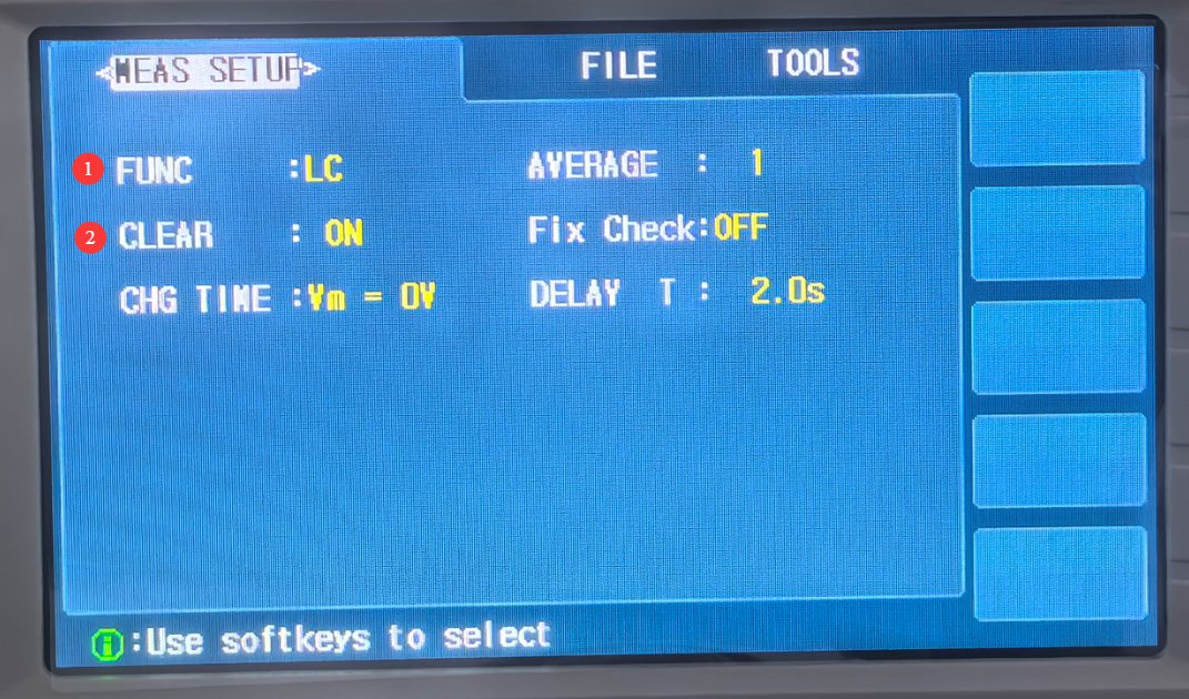
4.2 Interfață de setări
Vezi Figura 4-2.
| Număr | notițe |
|---|---|
| ① | To switch between test functions, use the arrow keys and soft keys to select a test function; you can switch between LC (Leakage Current Test) and IR (Insulation Resistance Test). |
| ② | Reset Switch: When performing a reset, make sure this switch is in the ON position. |
4.3 Interfață de sistem
Vezi Figura 4-3.
| Număr | notițe |
|---|---|
| ① | Alarm Sound Settings When Test Results Are Passing |
| ② | Alarm Settings When Test Results Are Unsatisfactory |
| ③ | Switch between English and Chinese in the interface |
| ④ | Keypress Sound Settings |
| ⑤ | Display Time Settings |
| ⑥ | Press F2 to display product information |
5. Steps for Testing Capacitors
5.1 Powering On and Preheating the Equipment
Press the power switch on the front panel to turn on the device.
After turning on the device, allow it to warm up for at least 20 minutes; wait until the internal circuitry has stabilized before performing accuracy tests. For routine quick checks, the warm-up time can be shortened, but measurement accuracy will be slightly reduced.
5.2 Preparing Equipment Parameters
5.2.1 Selection of Test Functions
As described in Section 4.2, you can switch between LC (leakage current test) and IR (insulation resistance test).
5.2.2 Setările parametrilor de testare
Refer to Section 4.1 to configure the required test parameters.
5.2.3 Zeroing Procedure
Refer to Sections 4.1 and 4.2 and perform the zeroing procedure as needed.
5.3 Connecting the Test Object
Verify that the device is in the discharged state and that the high-voltage indicator light is off.
Connect the red test lead to the INPUT (+) terminal and the positive terminal of the capacitor under test; connect the black test lead to the HV (-) terminal and the negative terminal of the capacitor under test.
Clamp the pins of the test object to ensure good contact; do not clamp pins that are oxidized, rusted, or greasy to prevent contact resistance from affecting the test results.
Once the connection is complete, keep your hands away from the test clamps and the metal parts of the pins.
5.4 Startup Testing and Data Reading
5.4.1 Test de pornire
Automatic Test Mode: Set the trigger mode to “Internal Trigger” and the test mode to “Automatic.” Press the [Charge/Start] button, and the device will automatically perform the complete “Charge → Test → Discharge” cycle. Once the test is complete, the device will automatically discharge without requiring any manual operation.
Pas cu pas Mod de testare: Set the trigger mode to “Internal Trigger” and the test mode to “Step-by-Step.” After pressing the [Charge/Start] button, the device will only perform charging and testing; it will not automatically discharge. Once the test is complete, you must manually press the [Discharge] button to release the high voltage. This mode is suitable for scenarios requiring extended-duration pressure testing.
5.4.2 Data Reading and Result Interpretation
During the test, the screen displays the following in real time: LC/IR: Leakage current / measured insulation resistance; Vm: Actual voltage across the current test object; Test status: Charging / Testing / Discharging.
After the test is complete, check the results on the right side of the screen: If “PASS” is displayed, the value is within the upper and lower limits, the product passes, and the green “PASS” light turns on; if “HIGH” is displayed, the value is above the upper limit, the product fails, and the red “FAIL” light turns on; if “LOW” is displayed, the value is below the lower limit, the product fails, and the red “FAIL” light turns on.
If the screen displays an out-of-range symbol, it indicates that the current range is insufficient; you must switch to a higher range and retest.
5.5 Ending The Test and Shutting Down
After the test is complete, press the [Discharge] button to confirm that the device has entered discharge mode and the high-voltage indicator light has turned off. Remove the test specimen and tidy up the test leads. Press the [Power Switch] on the front panel; the device will begin the shutdown process, and the screen will turn off. If the device will not be used for an extended period, unplug the power cord and neatly store the device and cables.
6. Întreținerea și îngrijirea zilnică a echipamentelor
6.1 Curățenie zilnică
6.1.1 Cleaning the Panel and Housing
Before cleaning, be sure to turn off the power and unplug the power cord, and wait until the device has cooled completely. Use a dry, soft cloth to wipe dust from the exterior, screen, and button surfaces; do not press hard on the screen, and do not use highly corrosive organic solvents such as acetone or thinners. For stubborn stains on the screen, gently wipe with a lint-free cloth dampened with a small amount of anhydrous ethanol, taking care to prevent liquid from entering the device.
6.1.2 Cleaning Test Terminals and Clamps
The metal terminals of the test clamp and the panel test terminals should be cleaned regularly to remove oxidation and oil residue, ensuring good contact. Wipe the metal contact surfaces with a cotton swab dipped in anhydrous ethanol, and allow them to air dry before use. Recommended cleaning frequency: once a month; once every two weeks for frequent use or in humid environments.
6.2 Daily Zero Calibration
You must perform a zero-calibration procedure whenever you replace the test leads, move the device, or experience significant changes in ambient temperature or humidity. If the device is used continuously for more than 8 hours, it is recommended that you perform a zero-calibration once during that period to ensure testing accuracy.
6.3 Specificații de depozitare
6.3.1 Cerințe privind mediul de stocare
The equipment should be stored in an environment with a temperature range of 5°C to 40°C and a relative humidity of ≤85% RH. The environment should be dry, dust-free, and free of corrosive gases. Avoid direct sunlight and keep the equipment away from strong magnetic fields and sources of vibration.
6.3.2 Operațiuni de depozitare pe termen lung
Before long-term storage, unplug all cables and clean the surface of the equipment and its terminals. Wrap the equipment in dust-proof film or its original packaging, and store it in a dry, well-ventilated area. Power on the equipment once a month for at least 10 minutes each time to remove internal moisture and prevent damage to components caused by moisture.
6.4 Cerințe privind intervalul de calibrare
To ensure the measurement accuracy and operational reliability of the equipment, it is recommended that it be sent periodically to a qualified third-party metrology organization for calibration. The recommended calibration interval is 12 months. Users may determine the specific calibration interval based on usage frequency, environmental conditions, and quality system requirements.
7. Depanarea și rezolvarea problemelor comune
| Simptome de eroare | Cauze posibile | Procedură |
|---|---|---|
| Nu se poate porni | Incorrect input voltage; fuse blown | Make sure the input voltage matches the voltage indicated on the input voltage selector switch on the back of the device; check the fuse, and if it is blown, replace it with a spare fuse. |
| Reset operation failed | The zero-reset switch in the test setup is not turned on, the test leads are not open-circuit, and the ambient temperature and humidity exceed the specified limits. | Refer to Section 4.2 to ensure that the zero-reset switch is turned on; check and ensure that the test leads are not shorted and are not connected to any device under test; move to a location where the ambient temperature and humidity meet the standards and try again. |
| Rezultate anormale ale testelor | Short circuit in the test lead, poor contact at the clamps, incorrect range setting, failure to zero the instrument, insufficient warm-up time, ambient temperature or humidity outside the specified range, insufficient charging time | Check for broken test leads and re-clamp the test probes; set the range to “Auto”; allow at least 20 minutes for warm-up; move to a test environment that meets the requirements; extend the charging time to ensure the capacitor is fully charged. |
| Unable to trigger the test | Incorrect trigger source settings, external trigger wire not properly connected, or the device is in a discharged state and has not started up | Check the trigger mode; set the manual test to internal trigger; check the trigger wiring in external trigger mode; press the Charge/Start button to start the test sequence |