
 Engleză
 中文简体
中文简体 Русский
 Español
 Português
 Türkçe
 العربية
 Deutsch
 Polski
 Italiano
 Français
 한국어
한국어 ไทย
ไทย Tiếng Việt
 日本語
日本語





























Tester automat de siguranță electrică
Manual de utilizare
Aplicabil LISUN modele: LS9955,LS9956
1. Despachetarea și familiarizarea de bază cu echipamentul
1.1 Specificații tehnice cheie
| Testarea tensiunii de rezistență AC și DC | Test de rezistență la izolație (IR) | ||||
| Intervalul de tensiune | Acuratețe | Gama de curent | Gama de rezistență la izolație | Acuratețe | Intervalul de tensiune |
| 100-4000 V | ± 3% | CA: 0.10–20.00 mA | 1.00–2000 MΩ | ± 3% | DC 100–1000 V |
| DC: 0.10–12.00 mA | |||||
| Test de curent de scurgere (LLC) | Ground Resistance Test (GR) | ||||
| Gama de curent de scurgere | Acuratețe | Intervalul de tensiune | Interval de rezistență la sol | Acuratețe | Iesire de curent |
| 0.10-20 mA | ± 0.3% | AC 10.0–300.0 V | 0–600 mΩ | ± 3% | AC 1.00–30.00 A |
| Power Test (POWER) (Note: The LS9955 does not include this feature) | |||||
| Voltaj | Curent | Alimentare | Factor de putere | Acuratețe | Timpul testului |
| 10-300 V | 0.010-20.00 A | 1.0–6000.0 V | 0.2-1.0 | Clasa de 0.5 | 0–999.9 s |
1.2 Despachetarea și verificarea conținutului
1.2.1 Despachetare și inspecție vizuală
Când despachetați dispozitivul, manipulați-l cu grijă pentru a evita zgârierea carcasei cu unelte ascuțite. După despachetare, inspectați mai întâi exteriorul dispozitivului pentru a vă asigura că nu există deformări sau lovituri vizibile și că butoanele nu sunt deteriorate sau slăbite. Dacă observați anomalii la dispozitiv sau la accesoriile sale, nu îl porniți. Vă rugăm să ne contactați imediat.
1.2.2 Gazdă și accesorii
Realizator: 1 LS9955/LS9956 gazdă.
Principalele componente sunt următoarele:
| Număr | notițe |
| ① Cablu de alimentare | |
| ② Test Kit | Power cord used to connect the device to the power source of the device under test |
| ③ Grounding Clamp | Used to connect the equipment to the grounded enclosure of the device under test |
| ④ Communication Cable | (If the software supports this feature) Used to connect the device to a computer. Note: Do not use this cable interchangeably with other RS-232 communication cables. |
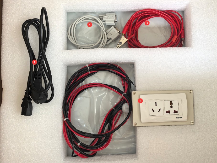
Figura 1
Download links for the electronic user manual, software, warranty card, and other materials have been sent via email. Please download them promptly. If you missed the email, you may contact us to request the download links again.
2 Măsuri de siguranță
2.1 Siguranța electrică
Cerințe de alimentare 2.1.1
Use a single-phase AC 220V ±10%, 50/60 Hz three-prong outlet; the ground prong must be connected to ground.
2.1.2 Cerințe de împământare
Firul de împământare al instrumentului este conectat fiabil la firul de împământare de protecție, iar rezistența la împământare de protecție este ≤4 Ω.
2.2 Siguranța mediului
2.2.1 Cerințe de temperatură și umiditate
Evitați utilizarea dispozitivului în medii în care umiditatea depășește 70% (fără condens) sau în care temperatura este în afara intervalului 0–35°C. Temperatura optimă de funcționare este de 25±2°C.
2.2.2 Contraindicații legate de mediu
Medii cu câmpuri magnetice puternice și câmpuri electrice puternice;
Medii care conțin gaze sau lichide corozive;
Zone cu praf inflamabil și exploziv și zone care conțin materiale periculoase;
Medii cu praf intens, temperaturi și umiditate ridicate și expunere directă la lumina soarelui.
2.3 Siguranța operațională
During testing, the casing of the test object is electrically charged; do not touch it with your bare hands under any circumstances;
Eșantionul de testare trebuie așezat pe un covoraș izolator din cauciuc;
Operatorii trebuie să poarte mănuși izolatoare din cauciuc;
Operators must have dry hands and must not wear any metal jewelry; eating or drinking is prohibited during testing to prevent accidents caused by electric shock;
Înainte de a înlocui obiectul de testat, trebuie mai întâi să opriți testul și să deconectați obiectul de testat de la sursa de alimentare de intrare;
Când sunt implicate mai multe persoane, definiți clar rolurile și responsabilitățile și confirmați-le reciproc înainte de a începe testul pentru a evita erorile.
2.4 Altele
Pentru aspectele care nu sunt acoperite de acest manual, vă rugăm să procedați cu prudență sau să ne contactați.
3. Proceduri de testare a siguranței
3.1 Standard Test Parameters (Reference: GB/T 7000.1-2023)
| Articole de testare | Prevederi standard corespunzătoare | Setări parametri de testare | Limite de acceptare | Timpul testului |
| Testul de rezistență la sol | 7 | Test Current: 25A | ≤0.1 Ω | 5s |
| Test de rezistență la izolație | 10.2 | Tensiune de testare: 500 V CC | ≥2 MΩ | Anii 60 |
| Testul de rezistență dielectrică (tensiune de rezistență) | Tensiune de testare: 1500 V CA | Fără defecțiuni, fără conturnare; curent de scurgere ≤ 5 mA | ||
| Testarea curentului de scurgere | 10.3 | Test voltage: 1.06 × rated voltage | ≤0.25 mA (standard products) | 10 seconds per phase, automatic phase switching |
Note: This manual uses GB/T 7000.1-2023 as an example only. If you are referring to other standards, please consult the corresponding standard for the correct test parameters.
3.2 Cablajul echipamentului
3.2.1 Introducere în panoul din spate și cablare
| Număr | notițe |
| ①② | Connect the device under test to its rated input power supply. For example, if the device under test is rated for 220 V, connect it to a 220 V regulated power supply. Note: The LS9956 is used to measure the power of the device under test; the LS9955 does not have this function and therefore does not need to be connected. |
| ③④ | Leakage current test voltage input. Note: Refer to Section 4.1; a voltage of 1.06 times the rated voltage must be applied for testing. For example, if the rated voltage of the device under test is 220 V, a 234 V regulated power supply must be used for the leakage current test. |
| ⑤ | Low-voltage startup test. The standard versions of the LS9955 și LS9956 do not have this feature; no connection is required. |
| ⑥⑦⑧⑨ | Connect the test box to the terminal block: terminals ⑥ and ⑦ are connected to the two red power wires from the test box, while terminals ⑧ and ⑨ are connected according to their respective shapes. |
| ⑩⑪ | Connect the ground clamp to the terminals, distinguishing between them based on their shape. Note: If the device under test does not have a ground wire, the ground clamp must also be connected to terminals ⑧ and ⑨, rather than terminals ⑩ and ⑪. |
| 10 | RS-232 communication port; if no software functions are required, there is no need to connect it. |
| 10 | Cablu de alimentare |
| 10 | Test Input Power Supply Circuit Breaker |
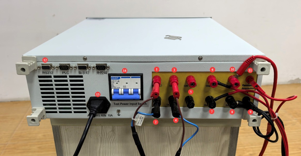
Figura 2
3.2.2 Conectarea obiectului de testare
Carcasa obiectului de testat trebuie să fie curată și fără ulei; așezați-o în centrul covorașului izolator, departe de suprafața metalică de lucru.
| Număr | notițe |
| ① | Connect the power cord of the device under test to the test kit. |
| ② | The grounding clamps must be attached to a metal part of the test object’s housing to measure ground resistance and withstand voltage. Note: If the test object has a ground wire, ensure that the metal part of the housing where the grounding clamps are attached is electrically connected to the test object’s ground wire. If there is no connection or the resistance is too high, when the earth clamps are used to test ground resistance, the device will display an “Open” message or indicate a test failure, meaning the device has failed the test; if the device does not have a ground wire, the earth clamps can be attached directly to the device’s housing and used solely for dielectric strength testing. |
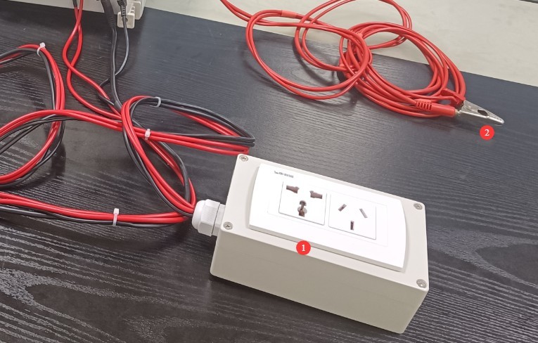
Figura 3
After all connections have been made and verified, turn on the circuit breaker on the back of the device.
3.3 Operarea panoului frontal
Porniți dispozitivul.
| Număr | notițe |
| ① | Use the left and right arrow keys to move the cursor |
| ② | The device can store a total of 199 sets of test data. First, move the cursor to the group number field and use the numeric keys to modify the group number. Note: You can overwrite data by using the same group number, or create a new test group using a different group number. |
| ③ | Continue moving the cursor to use the up and down arrow keys to modify the test items, and the number keys to modify the test parameters. Note: If the test object does not have a ground wire, there is no need to test the ground resistance; set this item to NULL. |
| ④ | Click “Save” to save the test parameters to the corresponding group number. The next time you run a test and need the same parameter settings, you can simply switch the test group number to the one you saved previously to retrieve them directly. |
| ⑤ | Once everything is set up, move the cursor to the page number. |
| ⑥ | Press the green Start button, and the device will automatically perform tests according to the configured test items, sequence, and parameters. |
| ⑦ | If you need to stop the test during the testing process, press the Stop button. |
| ⑧ | Status Indicator: During Testing, Test Passed, Alarm/Test Failed |
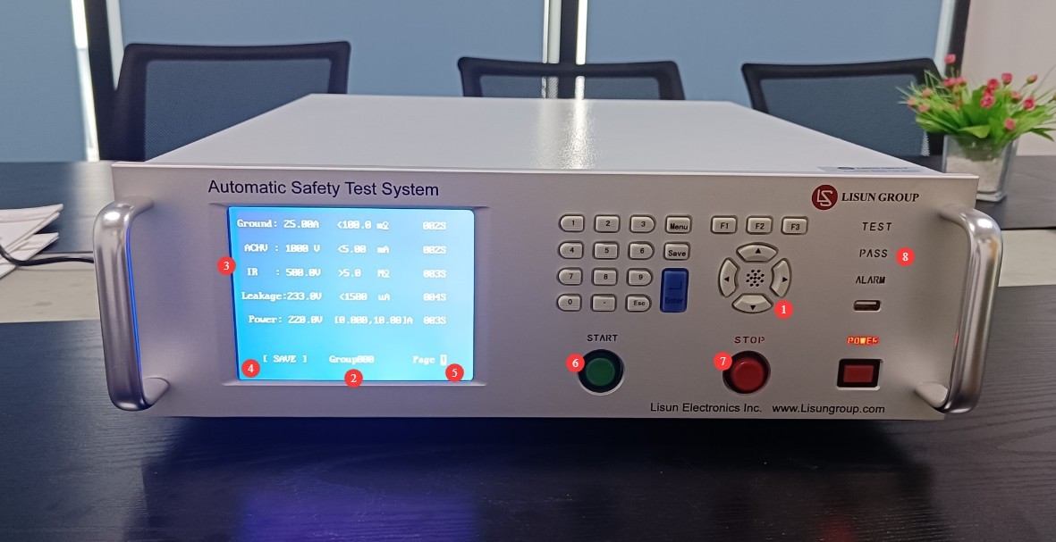
Figura 4
Note 1: For leakage current testing, the test voltage must be set to 234 V (using a 220 V test object as an example), i.e., it must match the leakage current test voltage of the connected device.
Note 2: For the LS9956 power test, the test voltage must be set to 220 V (using a 220 V device under test as an example), i.e., it must match the rated power supply of the connected device under test.
3.4 Common Equipment Alarms
3.4.1 NG
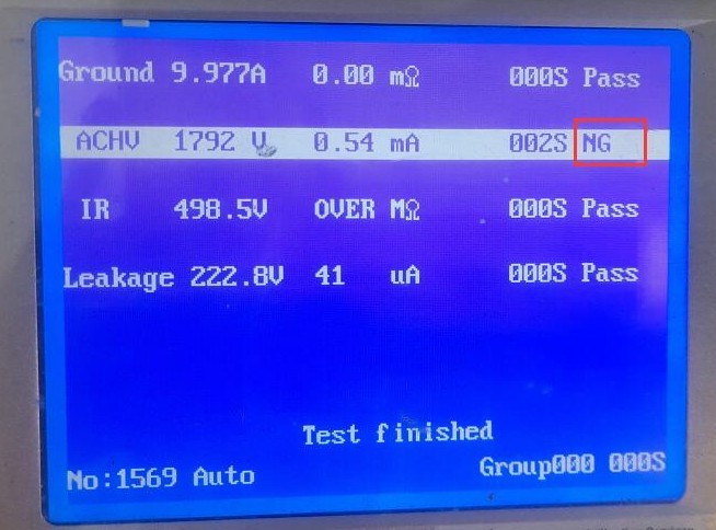
Figura 5
Failed the test.
3.4.2 PESTE
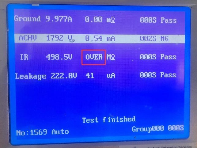
Figura 6
If the insulation resistance test value exceeds the equipment’s upper measurement limit (2000 MΩ), the test is considered passed.
3.4.3 Reglați
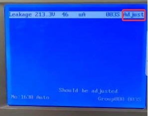
Figura 7
The leakage current test voltage input does not match the leakage current test voltage setting. Refer to sections 4.2.1 and 4.3 for adjustments.
3.4.4 Exceed current break
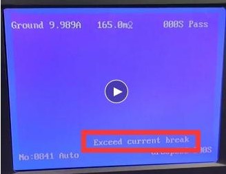
Figura 8
The current exceeds the equipment’s limit. Please check for a short circuit between the live wire, neutral wire, and ground wire of the device under test.
3.4.5 Deschis
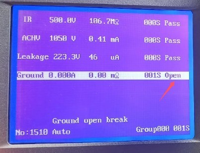
Figura 9
During the ground resistance test, an open-circuit error is displayed. Refer to Section 4.2.2 for adjustments.
3.5 Sfârșitul testării
3.5.1 Shutdown Procedure
Wait for the test to finish or press STOP to stop the test → Turn off the circuit breaker on the back panel → Shut down the unit.
3.5.2 Replacing the Test Object
Wait for the test to finish or press STOP to stop the test → Turn off the circuit breaker on the back panel → Replace the test object → Turn on the circuit breaker on the back panel → Set the parameters and run the test.
4. Utilizarea software-ului
4.1 Hardware Wiring Adjustments
4.1.1 Connecting the Communication Cables
Vezi 1.2.2.
4.1.2 Connecting the Test Power Supply
Dacă ați achiziționat un LISUN power supply and your device model is LS9956.
| Număr | notițe |
| ① | Conectați-vă la LISUN ieșire de alimentare |
| ② | Use the shorting cable provided with the LISUN device to short-circuit the rated power input terminal of the device under test to the leakage current test voltage input terminal. During the test, the LS9956 software automatically controls the power supply output to ensure that the power test and leakage current test are performed correctly. |
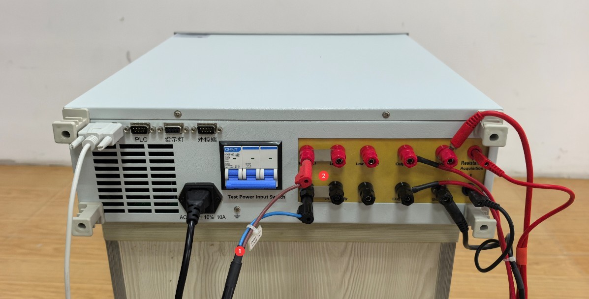
Figura 10
4.1.3 Connecting the Communication Cables
Dacă aveți o LISUN power supply, connect the LS9955/LS9956 communication cable and the LISUN power supply communication cable to the RS232 communication box, and then connect the communication box to your computer.
Dacă nu aveți un LISUN power supply, connect the LS9955/LS9956 communication cable to the RS232-to-USB adapter and then connect it to your computer.
Note: If your computer has enough RS232 ports, you do not need to use a communication box or a USB adapter cable.
4.2 Instalarea software-ului și a driverelor
| Număr | notițe |
| ① | LS9955/LS9956 Software: Double-click to install |
| ② | RS232 Communication Module Driver |
| ③ | RS232-USB Cable Driver |

Figura 11
instalarea RS232 Communication Box Driver.
| Număr | notițe |
| ① | Double-click it, then follow the on-screen instructions to install it. |
| ② | Please read the instructions on how to change the port. |
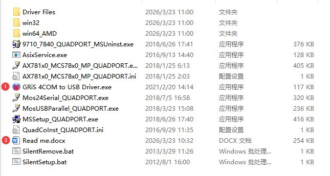
Figura 12
RS232-USB adapter cable driver—please double-click to install.
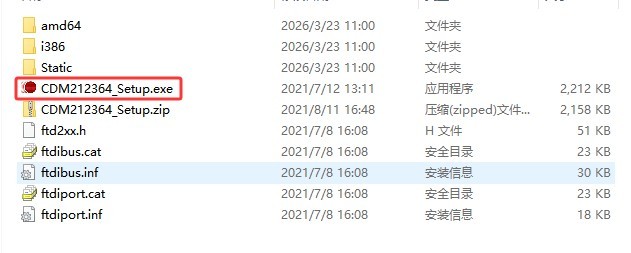
Figura 13
4.3 Setări software
4.3.1 Setări Port de Comunicare
Click to open the port settings screen.
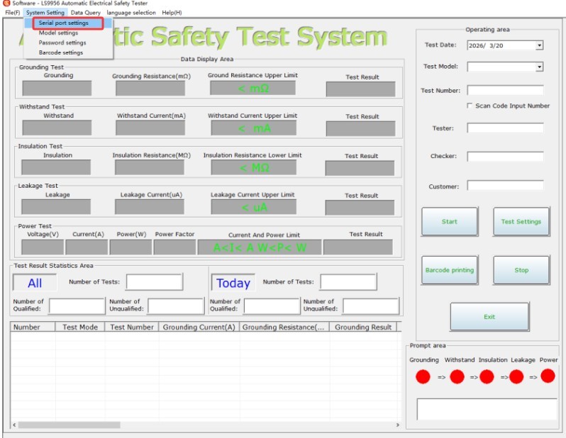
Figura 14
| Număr | notițe |
| ① | Dacă aveți o LISUN power supply, please check the box; if you do not have a LISUN power supply, please do not check the box. |
| ② | Click “Auto Search” to automatically detect the correct communication port for the LS9955/LS9956 și LISUN power supplies. Note: The software can only recognize port numbers less than 16. If the device’s port number is greater than 16, you will need to change it manually. If you are unsure how to do this, please ask your company’s IT department for assistance or contact us. |
| ③ | You can also manually select the correct communication port. |
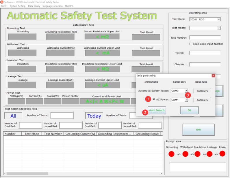
Figura 15
4.3.2 Setările parametrilor de testare
Accesați ecranul de setări ale parametrilor de testare.
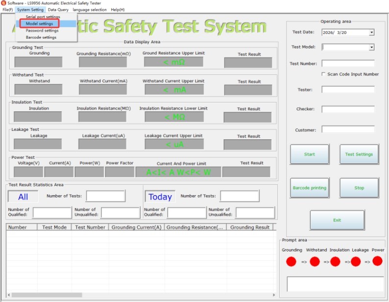
Figura 16
No password is required; just click “OK” to proceed.
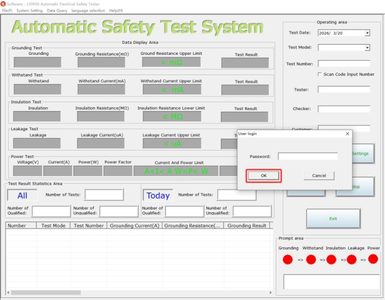
Figura 17
| Număr | notițe |
| ① | Click to change the model |
| ② | The model of the test item can be modified |
| ③ | Click to edit the limit |
| ④ | Editable Limit Groups |
| ⑤ | Enter product information |
| ⑥ | Set the required test parameters and test sequence |
| ⑦ | Click to Save Model |
| ⑧ | Click to save the limit group |
| ⑨ | Click here to exit |
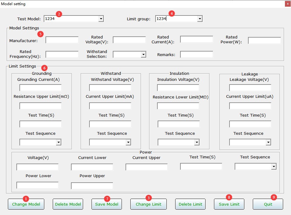
Figura 18
Take the model numbers and limit value groups included with the software as an example.
| Număr | notițe |
| ① | If a particular item does not require testing, change its test sequence to “No test.” |
| ② | The test sequences for the remaining test cases should be changed to start at 1. |
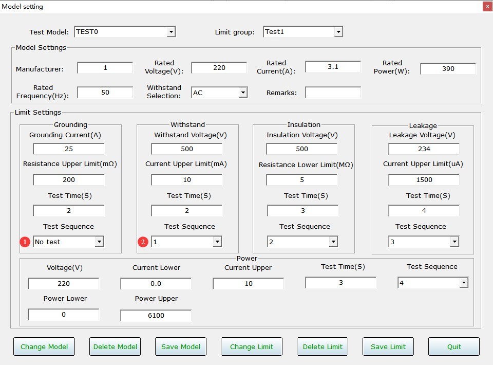
Figura 19
4.4 Test de pornire
4.4.1 Software Readiness
| Număr | notițe |
| ① | Select the model you want to test |
| ② | Clicking “Start” does not instruct the device to begin testing; rather, it indicates that the software is ready and can begin recording test data at any time. |
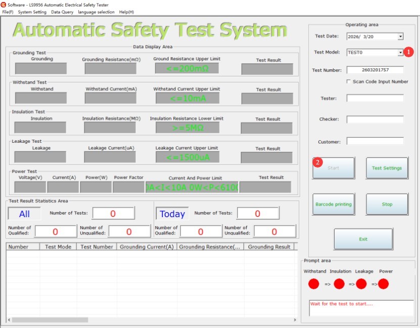
Figura 20
The test items and parameters for this test model in the software are automatically synchronized to the device.
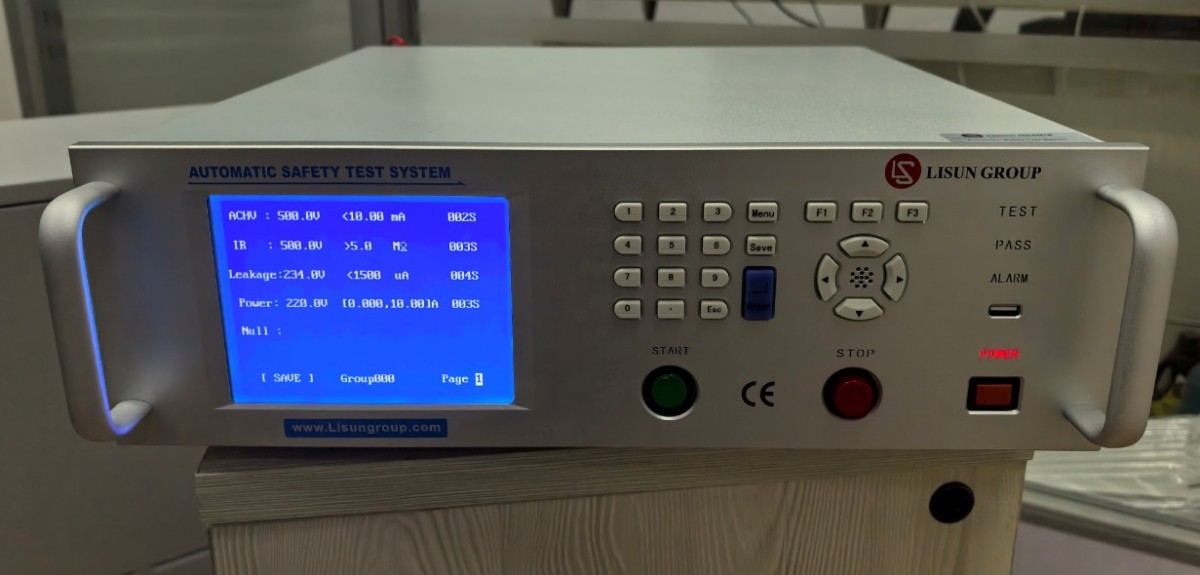
Figura 21
4.4.2 Hardware Execution Testing
After verifying that all connections are correct, turn on the circuit breaker on the back of the device. Then press the Start button on the front panel to begin the test.
You can repeat the test on the device, and the software will automatically record all test data.
4.5 Test Record Management
4.5.1 Real-Time Software Test Data
| Număr | notițe |
| ① | Both the software and hardware display the test status and progress; green indicates a passing test, while red indicates a test error or a failed test. |
| ② | All test data is saved automatically |
| ③ | Once the device has completed testing all samples, click “Stop,” and the software will stop recording data. |
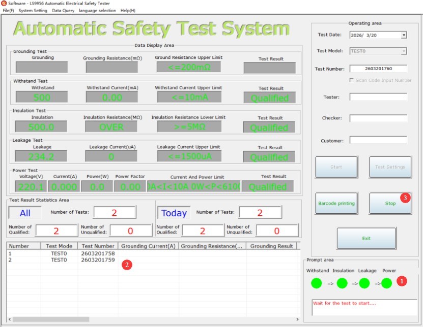
Figura 22
4.5.2 View Historical Test Data
| Număr | notițe |
| ① | Click to View Data |
| ② | You can set filter criteria |
| ③ | Click to filter all historical test data |
| ④ | You can preview, save, or print test data |
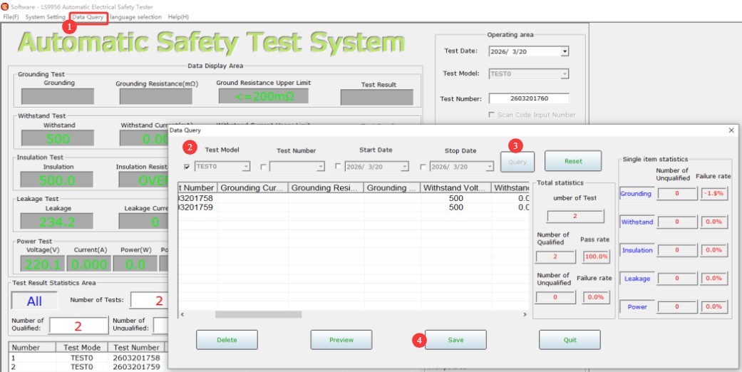
Figura 23
5. Întreținerea și îngrijirea zilnică a echipamentelor
5.1 Întreținerea de rutină
Before turning on the equipment, check that the exterior is clean and free of damage, that the cables show no signs of aging or breakage, and that the connectors are secure; Check the grounding clamps for oxidation or burnout; if present, wipe them with a specialized contact cleaner, and contact us to replace parts if necessary; after testing is complete, disconnect the power and wipe the equipment surface and the test area with a dry cloth.
5.2 Depozitare pe termen lung
When the device is not in use for an extended period, store it in a dry, well-ventilated area, away from moisture and direct sunlight; disconnect all cables, store accessories separately, and cover the device with a dust-proof cloth; power on the device for 30 minutes each month to prevent the internal electronic components from deteriorating.
6. Depanarea și rezolvarea problemelor comune
| Simptome de eroare | Cauze posibile | Procedură |
| Dispozitivul nu se va porni | Siguranță fuzibilă | Check the fuse in the equipment’s input power supply port; if it is blown, replace it with a fuse of the same model. |
| The device did not respond after I pressed the Start button. | The screen cursor is not on the page number | Once all parameters have been set, move the cursor to the page number before starting the test. |