
 Engleză
 中文简体
中文简体 Русский
 Español
 Português
 Türkçe
 العربية
 Deutsch
 Polski
 Italiano
 Français
 한국어
한국어 ไทย
ไทย Tiếng Việt
 日本語
日本語





























Goniofotometru cu rotație de înaltă precizie
Manual de utilizare
Aplicabil LISUN modele: LSG-1890B
1. Despachetarea și familiarizarea de bază cu echipamentul
1.1 Despachetare și inspecție
When unpacking the device, handle it gently to avoid scratching the casing with sharp objects. After unboxing, first inspect the exterior of the device to ensure there is no visible deformation or dents, and that the buttons are not damaged or loose. If you notice any abnormalities with the device or its accessories, do not turn it on. Please contact us immediately.
1.2 Configurarea și prezentarea generală a sistemului
1.2.1 Componente hardware de bază
Notă: Tabelul de mai jos prezintă componentele hardware de bază ale întregului sistem. Echipamentul achiziționat poate include doar o parte din aceste componente; vă rugăm să țineți cont de acest lucru atunci când urmați instrucțiunile din acest manual.
| Nume componentă | Model | Caracteristici de baza |
| Unitatea principală Goniofotometru | LSG-1890B | Used in conjunction with a photometric probe to measure photometric parameters and their spatial distribution, such as luminous flux and light distribution curves. |
| Sondă fotometrică de câmp apropiat | PM400C (N) | Potrivit pentru camere obscure standard, cum ar fi cele de aproximativ 10 metri |
| Far-Field Photometric Probe | PM400C (F) | Opțional. Potrivit pentru camere obscure extra lungi, cum ar fi cele mai lungi de 20 de metri. |
| Lumină standard | SLS-150W | Used to calibrate the darkroom (luminance sensor) |
| Corp de iluminat E27 | / | Pentru testarea C-Gamma; potrivit pentru becuri incandescente |
| Clemă transversală | Pentru testarea C-Gamma; potrivit pentru alte corpuri de iluminat de interior și exterior | |
| Clemă pătrată | Pentru testarea B-Beta; potrivit pentru proiectoare | |
| Laser cu linii încrucișate | Utilizat în timpul instalării și punerii în funcțiune; utilizat în timpul calibrării și testării pentru a determina poziția și orientarea lămpii standard și a corpului de iluminat eșantion | |
| Cabinet | CASE-19 | Used to house angle controllers, power meters, and DC and AC power supplies. Includes a power strip, an RS485 communication module, and more. |
| Controler de unghi | RT-200C | Unghiul la care este poziționat Goniofotometrul pentru afișare și control. În general, nu este necesară nicio ajustare manuală; controlul este gestionat de software. |
| Masurator de putere | Seria LS | Măsurați parametrii electrici precum tensiunea, curentul, puterea și factorul de putere al probei |
| Sursă de alimentare DC | Seria DC | Oferă o sursă de alimentare DC stabilă pentru mostre DC, lămpi standard și lămpi auxiliare |
| Putere de curent alternativ | Seria LSP | Oferă o sursă de alimentare CA stabilă, cu undă sinusoidală pură, pentru probele de CA |
1.2.2 Software, manuale, certificate etc.
At the time of shipment, a download link containing all the documents was sent via email. Please download them promptly. If you missed the email, you can contact us to request a new download link.
Include software, manuale de utilizare, carduri de garanție, certificate de calibrare a lămpilor standard și alte documente importante, precum și alte documente relevante.
1.4 Parametrii de măsurare
Illuminance data, illuminance distribution, area luminous flux, luminaire efficiency, luminance distribution (optional), utilization factor, luminance limit curve, glare rating, isophote curves, maximum allowable height-to-distance ratio, luminaire curve vs. illumination area, isointensity curves, effective beam angle, EEI, UGR, PAR, PPF, and PPFD spatial distribution tests, etc.
2. Note importante
2.1 Siguranța electrică
The system must be connected to a stable AC power source rated at 220 V ±5% with a frequency of 50 Hz or 60 Hz. Ensure proper grounding with a grounding resistance of ≤4 Ω. Do not use the equipment if the power connections are loose or the cables are damaged.
2.2 Siguranța mediului
Când se utilizează camera obscură optică, temperatura ambiantă trebuie menținută la 25±1°C, iar umiditatea relativă trebuie menținută între 10% și 65% RH;
Atât camera de control, cât și camera obscură trebuie să fie păstrate uscate, bine ventilate, fără praf și fără gaze corozive;
Avoid placing the device near strong magnetic or electric fields; it must be placed on a level, sturdy surface.
2.3 Proceduri de operare în camera obscură
2.3.1 Descrierea camerei obscure
Please confirm that the darkroom has been constructed exactly according to the darkroom drawings we provided. If there are any discrepancies in the actual dimensions, please inform us before installing and commissioning the equipment so that we can adjust the plan, ensuring that the installation and commissioning proceed smoothly and that the test results are accurate;
The interior of the darkroom must be completely painted matte black—that is, a non-reflective pure black—including all walls, ceilings, floors, partitions, doors, and so on. A small number of components, such as lighting fixtures, air conditioning units, and power switches, may not be painted black, provided they do not appear in the optical path between the Goniophotomoeter’s main unit and the photometric probe;
Once the equipment has been installed and commissioned, do not move any of the hardware components inside the darkroom, including the main unit base, the photometer probe base, the photometer probe orientation, and the cross-laser base. Doing so may result in inaccurate test results.
2.3.2 Precautions for Using the Darkroom
Scoateți-vă pantofii sau puneți-vă huse pentru încălțăminte când intrați în camera obscură pentru a preveni introducerea prafului;
Corpul de iluminat eșantion trebuie montat în siguranță pentru a preveni căderea și deteriorarea Goniofotometrului în timpul testării;
Do not place any objects on the main unit of the Goniophotomoeter, and do not place any objects within the Goniophotomoeter’s rotation range;
În timpul testării, camera obscură trebuie să rămână sigilată pentru a preveni interferența luminii externe cu rezultatele testului.
2.3.3 Precauții atunci când camera obscură nu este utilizată
Keep the darkroom closed; unauthorized persons are not allowed to enter; prevent dust from entering the darkroom.
2.4 Proceduri standard de funcționare a lămpii
The standard lamp has a lifespan of one year and is used for calibrating the photometer probe in a darkroom during installation and commissioning;
Dacă laboratorul dumneavoastră trebuie să își calibreze anual camera obscură, puteți achiziționa o nouă lampă standard;
Lampa standard este fierbinte imediat după utilizare; nu o atingeți. Lăsați-o să se răcească timp de 10 minute înainte de a o pune înapoi în carcasa lămpii;
The standard lamp used in the darkroom is a directional standard lamp, and its direction is controlled by its bracket. Do not remove the bulb from its bracket; doing so will render the standard lamp inoperable.
2.5 Altele
Pentru aspectele care nu sunt acoperite de acest manual, vă rugăm să procedați cu prudență sau să ne contactați.
3. Ansamblu hardware
3.1 Asamblarea echipamentelor din dulap
3.1.1 Introducere în Cabinet
Așezați dulapul pe o bancă de lucru plană și stabilă, lăsând suficient spațiu pentru utilizare.
| Număr | notițe |
| ① | Schemă de conectare: Vă rugăm să asamblați echipamentul conform schemei de conectare. |
| ② | Panou de distribuție a energiei, utilizat pentru conectarea cablurilor de alimentare ale tuturor dispozitivelor din interiorul dulapului |
| ③ | Cablu de alimentare al ventilatorului de răcire: Vă rugăm să îl conectați la prelungitorul din interiorul dulapului. |
| ④ | Cutie de comunicare RS-485, utilizată pentru conectarea tuturor dispozitivelor printr-un cablu de comunicare RS-485 |
| ⑤ | Vă rugăm să conectați adaptorul de alimentare pentru cutia de comunicare RS485 la prelungitorul din interiorul dulapului. |
| ⑥ | The USB cable for the RS485 communication box must be connected to the computer. |
| ⑦ | Cablare controler unghiular RT-200C |
| ⑧ | Cablajul contorului de putere din seria LS |
| ⑨ | Conexiune de alimentare DC |
| ⑩ | Cablaj de alimentare AC |
| ⑪ | The main power cable for the cabinet, which supplies power to all equipment inside the cabinet, should be routed out through cable opening ② and connected to the power source only after all equipment has been fully assembled. |
| 10 | Cable opening—the main power cord can be routed through here. Note: The main power cord plug is a Chinese standard plug; you may need to provide your own power adapter. |
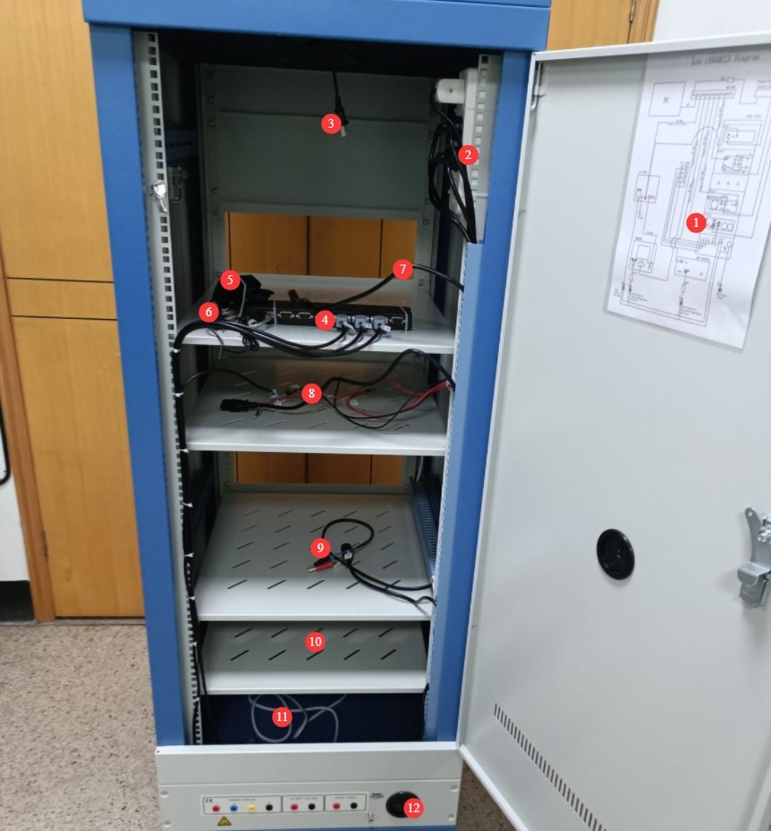
Figura 1
3.1.2 Instalarea RT-200C
Deocamdată, tot ce trebuie să faci este să îl conectezi.
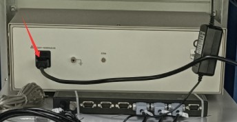
Figura 2
3.1.3 Instalarea contorului de energie LS
| Număr | notițe |
| ① | Connected via an RS-485 communication cable; the other end is connected to the RS-485 communication box inside the cabinet. |
| ② | Cablul de alimentare este conectat; celălalt capăt este deja conectat la panoul de distribuție a energiei din interiorul dulapului. |
| ③ | Cablul de testare V1, conectat la terminalul roșu al tensiunii V a contorului de energie electrică |
| ④ | Cablul de testare V2, conectat la terminalul negru al tensiunii V a contorului de energie electrică |
| ⑤ | Cablul de testare A1, conectat la terminalul roșu al contorului de curent A |
| ⑥ | A2 test lead, connected to the black terminal for current A on the power meter |
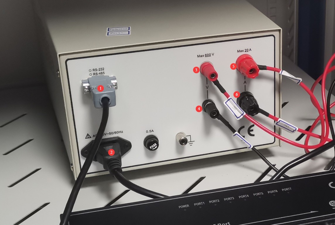
Figura 3
3.1.4 Instalarea sursei de alimentare CC
| Număr | notițe |
| ① | Conectat printr-un cablu de comunicație RS-485; celălalt capăt este deja conectat la cutia de comunicație RS-485 din interiorul dulapului. |
| ② | Conectați firele de ieșire de curent continuu, asigurându-vă că bornele pozitive și negative se potrivesc. |
| ③ | Cablul de alimentare este conectat; celălalt capăt este deja conectat la prelungitorul din interiorul dulapului. |
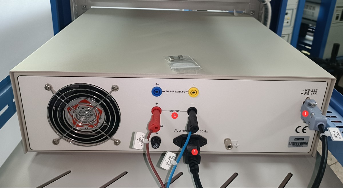
Figura 4
3.1.5 Instalarea alimentării cu curent alternativ
Please locate the following AC power output cable in the accessories:
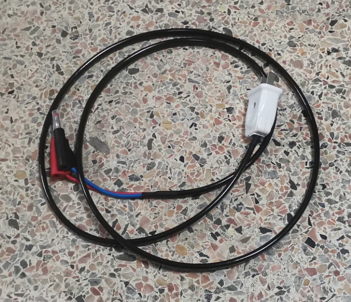
Figura 5
| Număr | notițe |
| ① | Connected via an RS485 communication cable; the other end is already connected to the RS485 communication box inside the cabinet. |
| ② | Cablul de alimentare este conectat; celălalt capăt este deja conectat la prelungitorul din interiorul dulapului. |
| ③ | Treceți cablul de ieșire a alimentării CA prin orificiul pentru cablu ④ și conectați-l la poziția ⑤. |
| ④ | Gaura firului |
| ⑤ | AC power output cable: Pass it through cable hole ④ and connect it to position ③. |
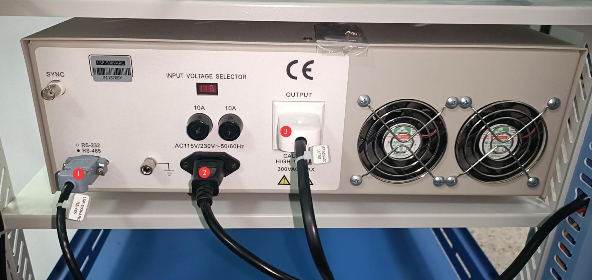
Figura 6
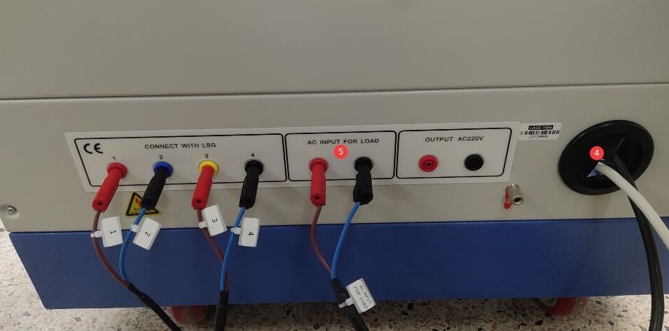
Figura 7
3.2 Installation of The Goniophotomoeter Main Unit and Goniophotomoeter Probe
3.2.1 Host Assembly
The same number is engraved on the main unit’s base tapered sleeve ① and the corresponding position on the main unit ②. Rotate the tapered sleeve until the two numbers are aligned, then secure the tapered sleeve using the hex socket screws provided as standard.
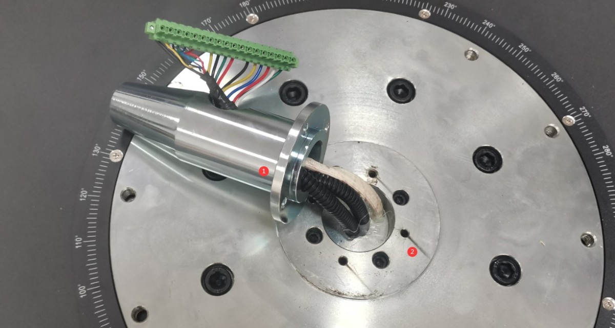
Figura 8
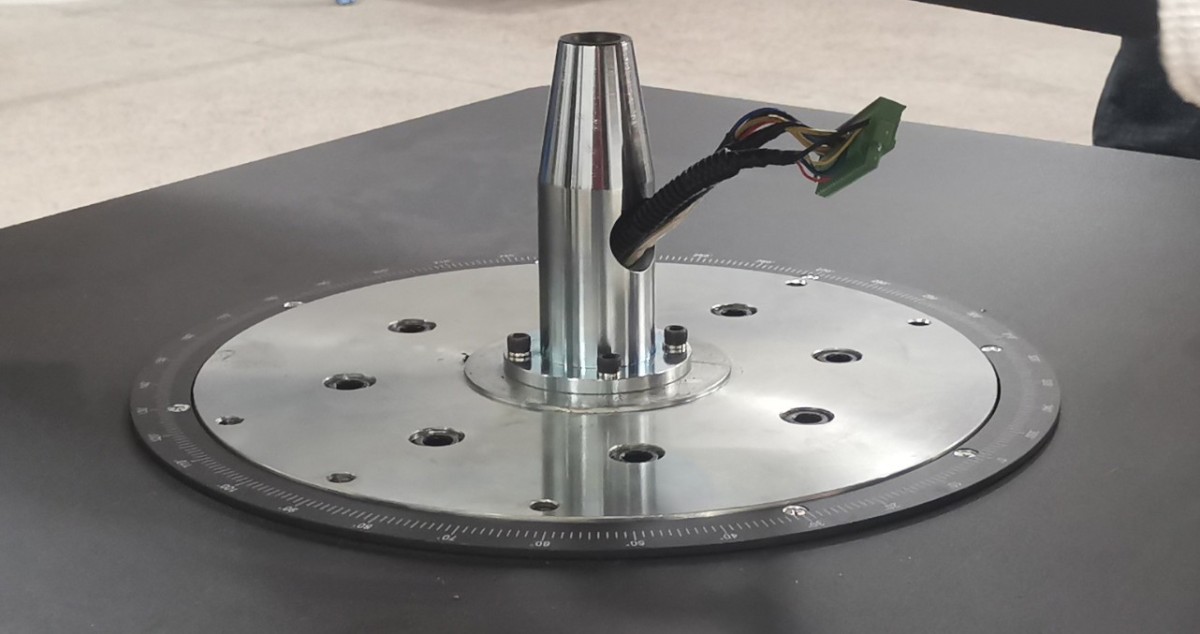
Figura 9
Remove the screws securing the dust cover on the turntable, and pull the dust cover off.
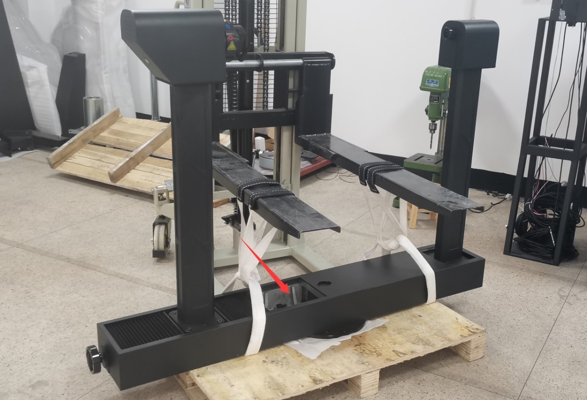
Figura 10
Use a forklift to lift the turntable; since the turntable is quite heavy, three to four people can also carefully lift it. Align the dust cover on the turntable with the terminal block on the base, then slowly lower the turntable onto the base. Hold the terminal block in place with your hand so that it slides into the turntable along with the tapered sleeve, preventing the terminal block from being crushed by the turntable.
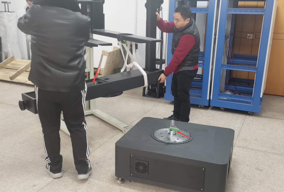
Figura 11
To fine-tune the turntable’s direction, follow these steps in the order listed below.
| Număr | notițe |
| ① | Align the six screw holes on the turntable with the six screw holes on the base, and use the standard hex screws and washers provided to secure the turntable to the base . Note: Be sure to use all the standard washers; otherwise, the screws may not fit properly, which could damage the equipment during turntable rotation. |
| ② | Plug the base terminal block into the corresponding terminal block socket on the turntable. |
| ③ | Then put the dust cover back in place |
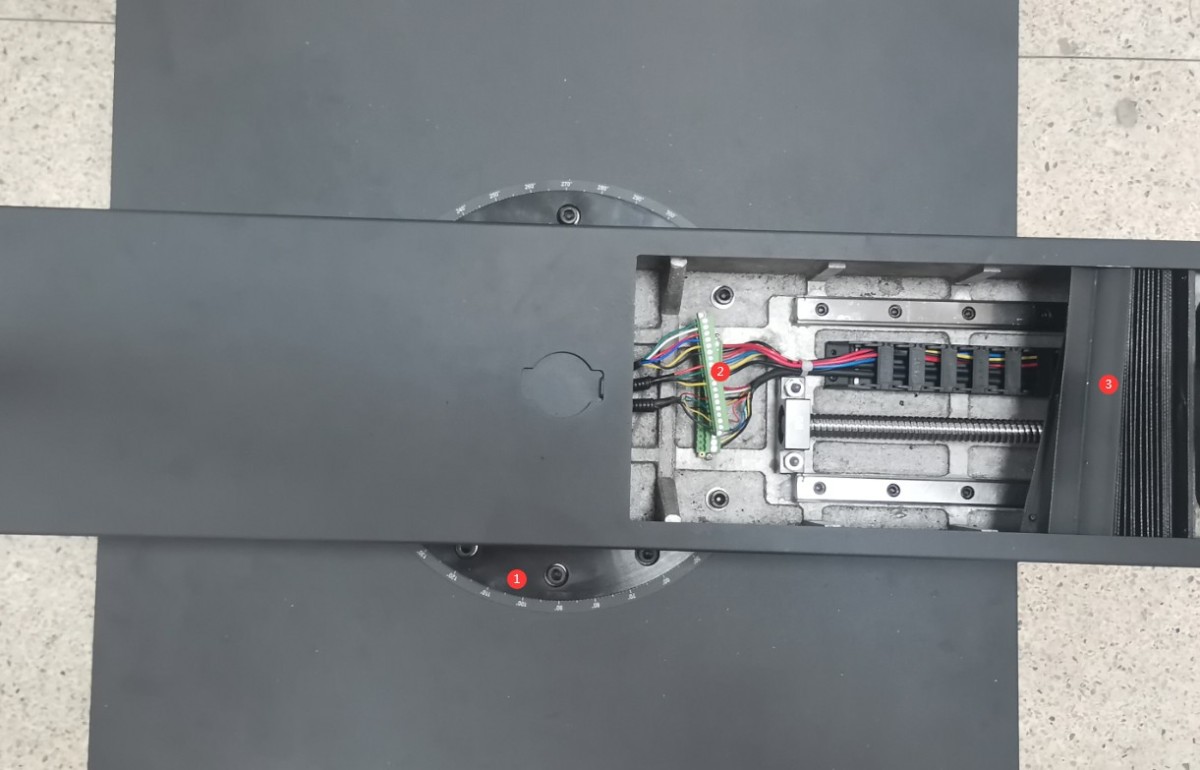
Figura 12
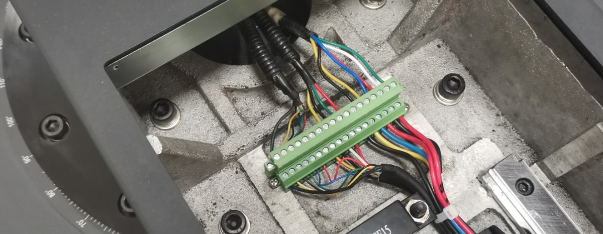
Figura 13
The four feet on the bottom of the unit are height-adjustable.
| Număr | notițe |
| ① | Rotiți șurubul din partea de jos pentru a ridica piciorul până când acesta se detașează de sol. |
| ② | În același timp, asigură-te că șurubul de sus nu apasă pe nimic; îl poți deșuruba ușor. |
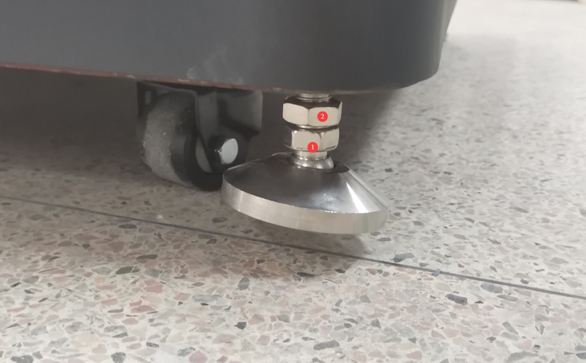
Figura 14
Position the goniophotomoeter in the correct location according to the darkroom blueprints. Align the four sides of the base as closely as possible with the darkroom walls. Then remove the auxiliary arm.
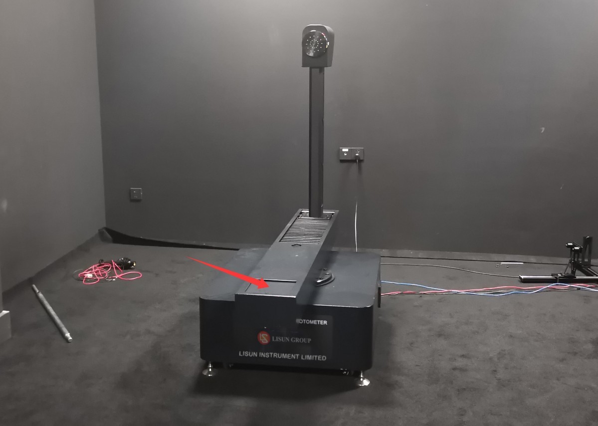
Figura 15
Apoi, rotiți toate cele patru picioare ale Goniofotometrului până când acestea intră în contact cu podeaua.
3.2.2 Assembly of the Photometric Probe and Probe Holder
Take, for example, a darkroom with only one photometer.
Asamblați sonda fotometrică și suportul sondei și poziționați-le în locațiile corespunzătoare conform desenelor camerei obscure; nu este nevoie să le fixați cu șuruburi deocamdată.
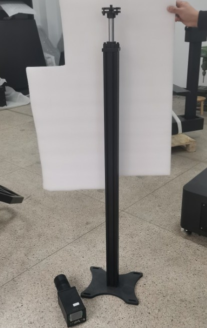
Figura 16
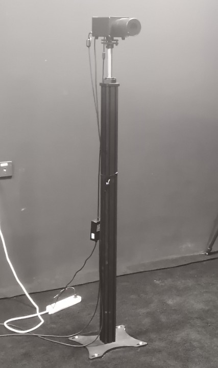
Figura 17
3.2.3 Cablajul sistemului
| Număr | notițe |
| ① | The four terminal blocks ①on the cabinet are connected to the Goniophotomoeter⑩; simply match them one-to-one based on the numbers. |
| ② | The two terminals connect to the terminal block inside the cabinet and are used to supply power to all equipment in the darkroom, including the Goniophotomoeter and photometric probes. This allows for convenient control of all darkroom equipment via the cabinet’s power switch. Note: The darkroom equipment can also be powered directly from the mains. |
| ③ | Terminal de împământare al dulapului: Vă rugăm să îl conectați la masă folosind un fir. |
| ④ | Cablu de alimentare pentru dulap, conectat la o sursă de alimentare de 220V, 50/60 Hz |
| ⑤ | Cablu de alimentare pentru unitatea principală a goniofotometrului |
| ⑥ | Conectați terminalul de împământare al Goniofotometrului la masă folosind un fir. |
| ⑦ | This is a one-to-two communication cable; one end of the RS-485 cable connects to the RS-485 communication box inside the cabinet, and the other end connects to position ⑭ on the back of the RT-200C. |
| ⑧ | Firul de declanșare al sondei fotometrului; conectați la sonda ⑬. Când este instalată o singură sondă, setarea implicită este câmp apropiat (N). |
| ⑨ | If you have only one photometer in your darkroom, there is no need to connect the far-field (F) sensor. |
| ⑩ | Cele patru blocuri terminale ⑩de pe Goniofotometru sunt conectate la carcasă①; pur și simplu potriviți-le unul cu unul conform numerelor. |
| ⑪ | Power Adapter for Photometric Probe |
| 10 | Cablu de comunicație RS-485 pentru sonda fotometrică; celălalt capăt se conectează la cutia de comunicație RS-485 din interiorul dulapului |
| 10 | Cablu de declanșare a sondei fotometrice, conectat la unitatea principală ⑧ a Goniofotometrului |
| 10 | RT-200C communication cable, with the other end connected to the main⑦ unit of the Goniophotomoeter |
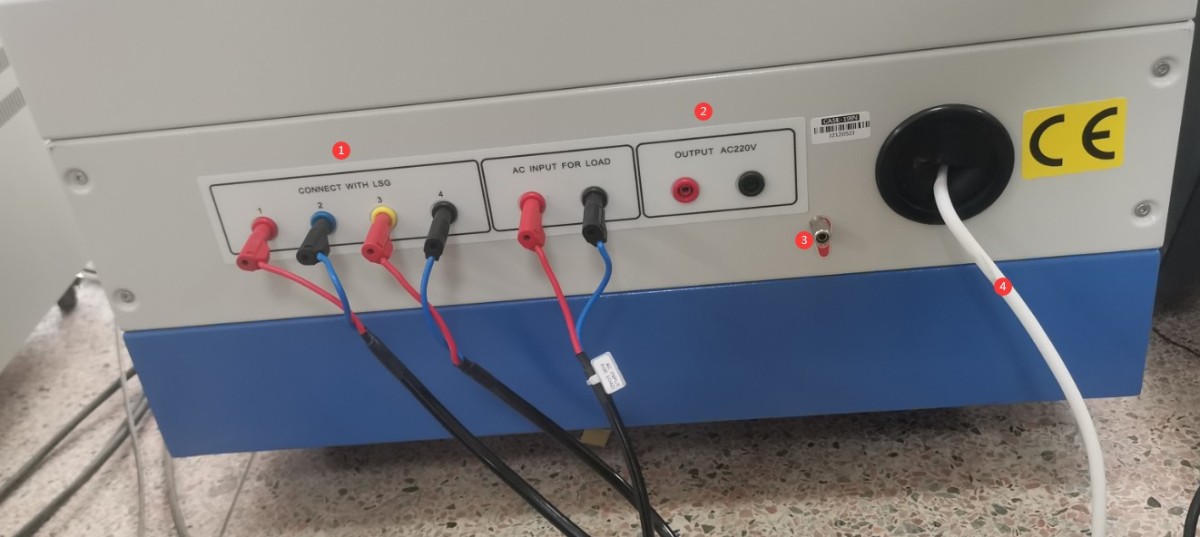
Figura 18
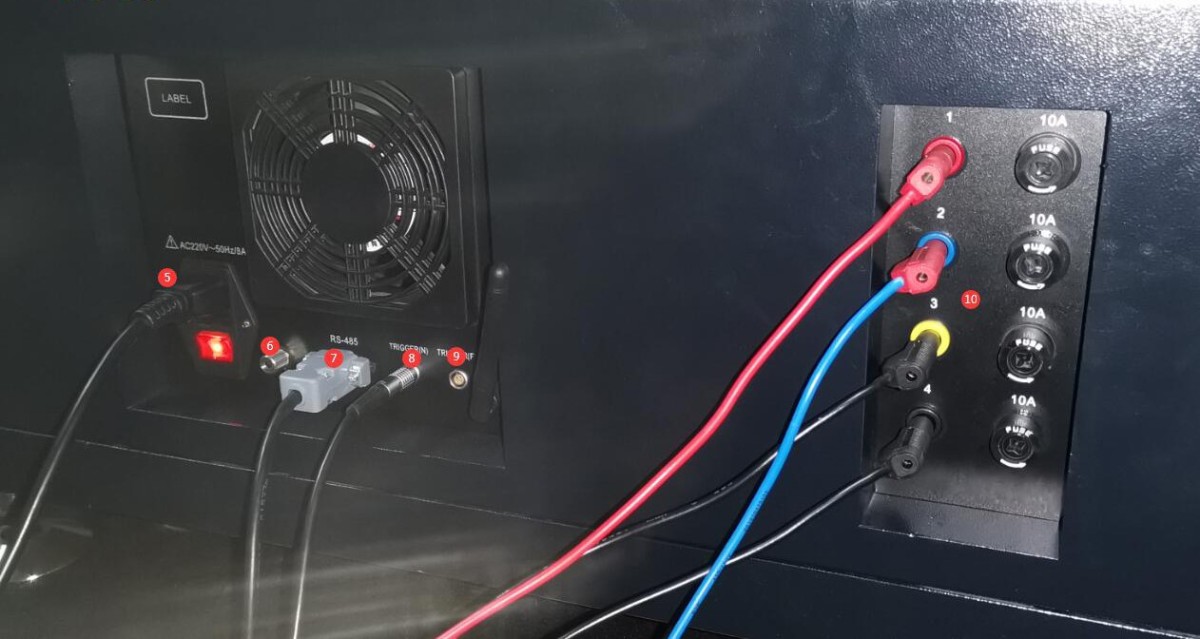
Figura 19
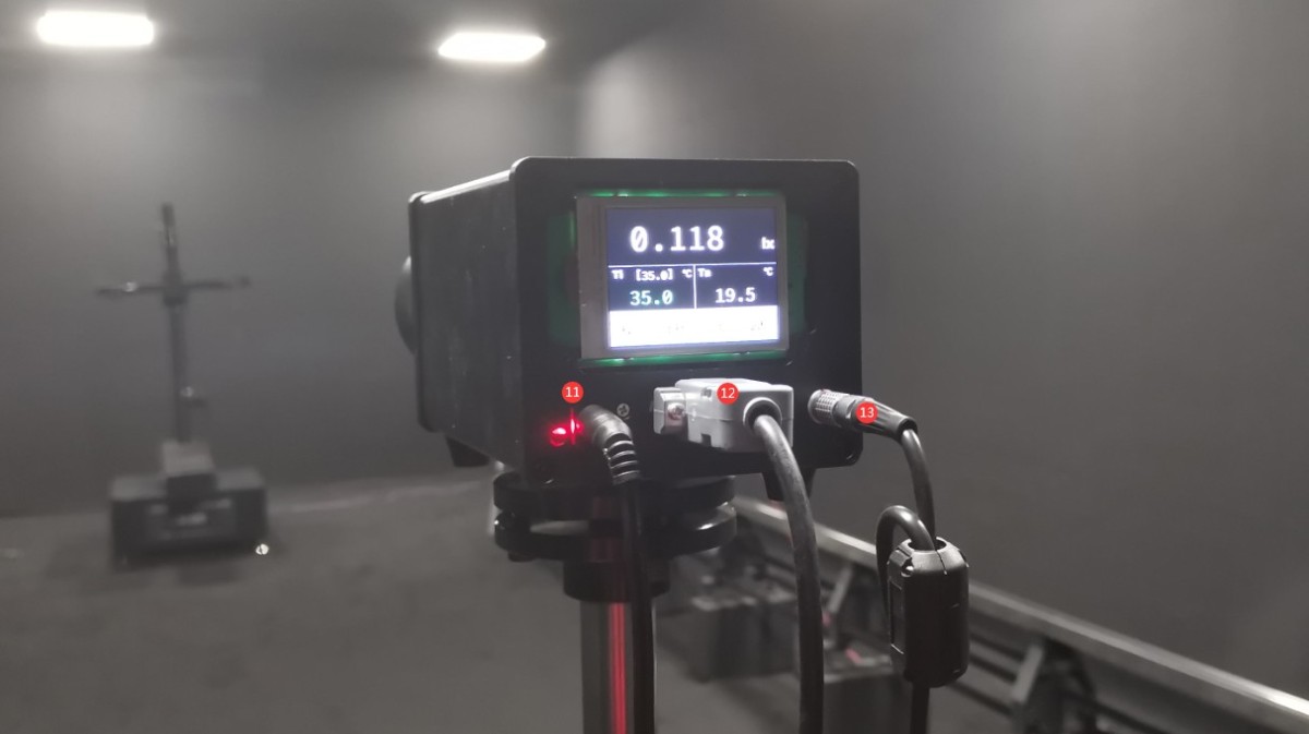
Figura 20
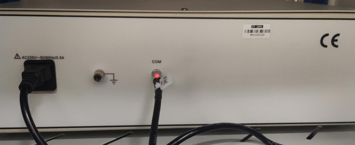
Figura 21
4. Instalare și configurare software
4.1 Instalarea software-ului și a driverelor
4.1.1 Mediul de execuție software
Cerințe de sistem: Windows 7/8/10/11 (32 biți/64 biți); computerul trebuie să aibă cel puțin un port USB.
4.1.2 Instalare
| Număr | notițe |
| ① | LSG Series Goniophotomoeter Software—Double-click to install |
| ② | Acest fișier APK poate fi copiat pe un telefon Android pentru instalare. Aplicația este destinată exclusiv rotirii Goniofotometrului și nu poate fi utilizată pentru testare. Deoarece software-ul include toate funcțiile aplicației, acest manual folosește software-ul ca exemplu de funcționare. |
| ③ | RS485 Communication Box Driver—Please double-click to install |
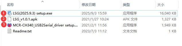
Figura 27
4.1.3 Gestionarea excepțiilor
If your antivirus software or the Windows Firewall flags a file as suspicious during the software installation process, please temporarily disable the antivirus software or the Windows Firewall and try installing the software again.
If the software fails to open when you double-click its icon after a successful installation, please check whether you are logged in to your computer with an administrator account. If the software still does not open after logging in with an administrator account, right-click the software icon to open its Properties window. On the Compatibility tab, check the box next to “Run this program as an administrator,” click “Apply,” and then double-click the icon again to open the software.
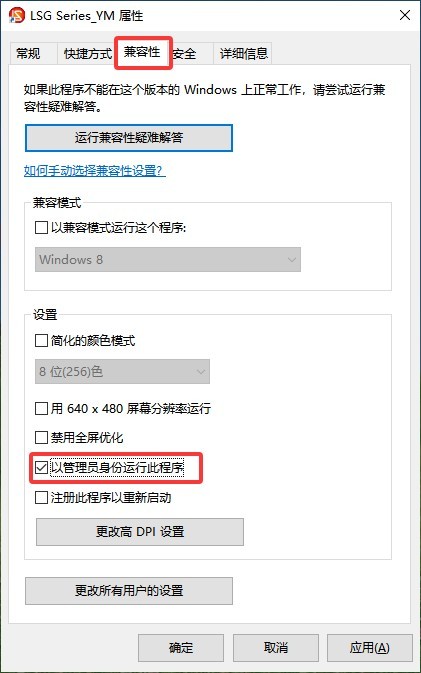
Figura 28
4.2 Setări software
First, turn on the cabinet’s power switch, then power on all system devices, including all equipment inside the cabinet, the Goniophotomoeter main unit, and the photometric probes. Double-click to launch the software. The first time you run the software, it will automatically open the system configuration interface. Select the correct model for each device you have purchased.
| Număr | notițe |
| ① | To select a goniophotomoeter model, click the drop-down list on the right. The model you purchased is the LSG-1890B. |
| ② | Sondă fotometrică în câmp apropiat; selectați modelul de sondă fotometrică PM400C |
| ③ | Sondă fotometrică de câmp îndepărtat — dacă nu ați achiziționat una, selectați „Neinstalată”. |
| ④ | LSG-1890B does not include a near-field Spectroradiometer; please select “Not Installed.” |
| ⑤ | AC power supply models are generally from the LSP Series |
| ⑥ | Modelele de surse de alimentare CC sunt în general denumite seria CC |
| ⑦ | Modelul contorului de energie: Numărul modelului este imprimat pe panoul frontal al contorului de energie. Vă rugăm să îl verificați și să selectați modelul corespunzător. |
| ⑧ | După ce ați selectat toate modelele corecte, faceți clic pe „Detectare automată port”. |
| ⑨ | După finalizarea căutării tuturor porturilor, faceți clic pe „OK” pentru a salva și a ieși. |
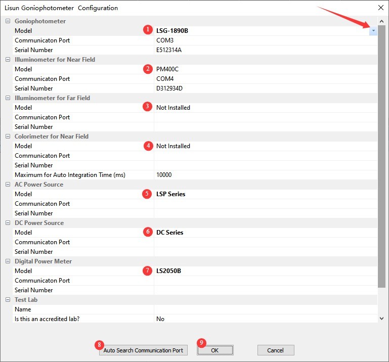
Figura 29
Note: If a communication error occurs during the automatic port search, please read the error message carefully, check whether the corresponding device is powered on, and verify that the RS485 communication cable is properly connected. Once you have confirmed these points, click “Automatic Port Search” again until communication is established with all devices.
After clicking OK, the software automatically opens the database file save dialog. From then on, all test reports will be automatically saved in this database file.
| Număr | notițe |
| ① | Selectați calea în care doriți să salvați fișierul bazei de date. Nu îl salvați pe desktop sau în folderul Desktop. |
| ② | Introduceți numele fișierului |
| ③ | Pur și simplu faceți clic pe „Salvare” |
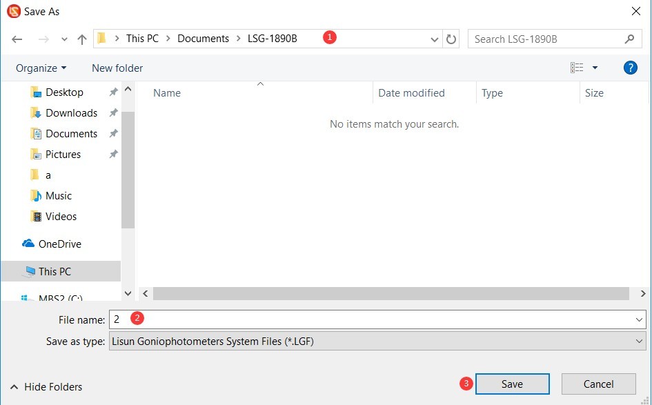
Figura 30
5. Calibration of darkroom equipment (Each step must be performed carefully and thoroughly; otherwise, calibration data may be inaccurate and test results may be abnormal.)
5.1 Horizontal Commissioning of the Main Unit
5.1.1 Laser Ready
There is a laser switch on the back of the goniophotomoeter’s main arm. When you turn on the line laser switch, you will see a red line laser beam emitted directly in front of the main arm.
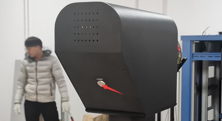
Figura 31
Find the crosshair laser device and tripod.
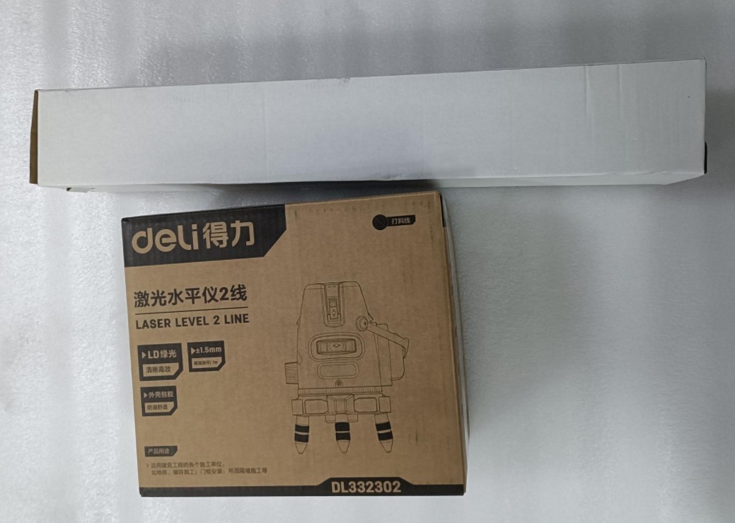
Figura 32
Remove the cross-line laser and the batteries. Insert the batteries into the cross-line laser. The power switch is located on the side of the device. The device turns on when the switch is set to the “unlocked” position.
| Număr | notițe |
| ① | Întrerupător de alimentare: Rotiți-l în poziția „Deblocare” pentru a porni alimentarea. |
| ② | VH se referă la comutatoare laser verticale, respectiv orizontale. |
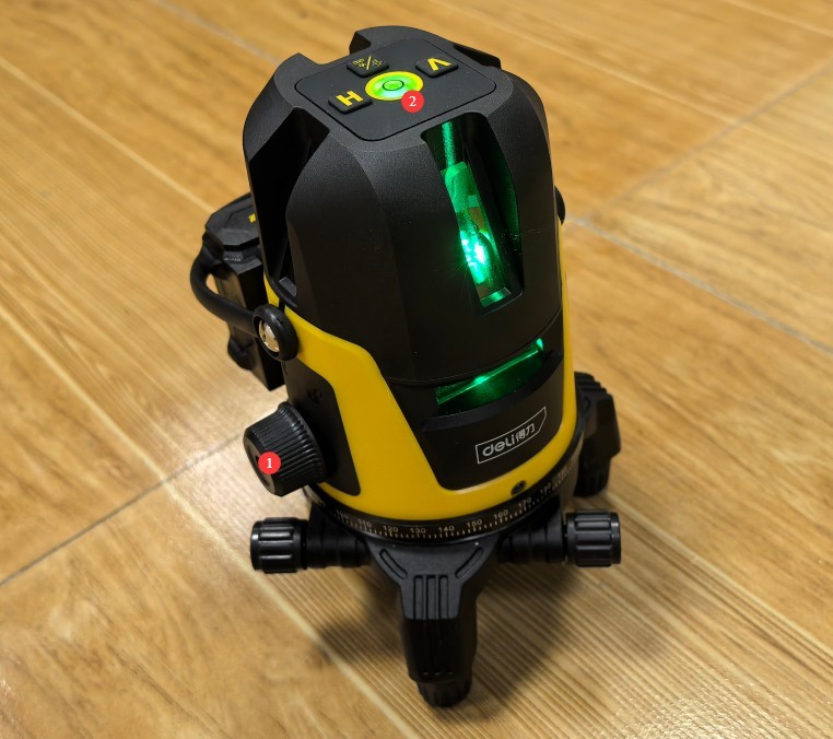
Figura 33
Mount the crosshair laser onto the tripod.
Note: The cross-line laser is self-leveling. If the cross-line laser is not self-leveled, an audible alarm will sound. This may be due to an uneven surface or a tripod that is not properly set up. Please ensure that the cross-line laser remains self-leveled at all times during use.
5.1.2 Pași pentru punerea în funcțiune orizontală a mașinii gazdă
Conform desenelor din camera obscură, înălțimea centrală a LSG-1890B goniophotomoeter is 1510 mm. Using a tripod, adjust the height of the horizontal laser beam from the crosshair laser to 1510 mm. At this height, the horizontal laser beam should pass through the center of all light-transmitting holes in the darkroom partition.
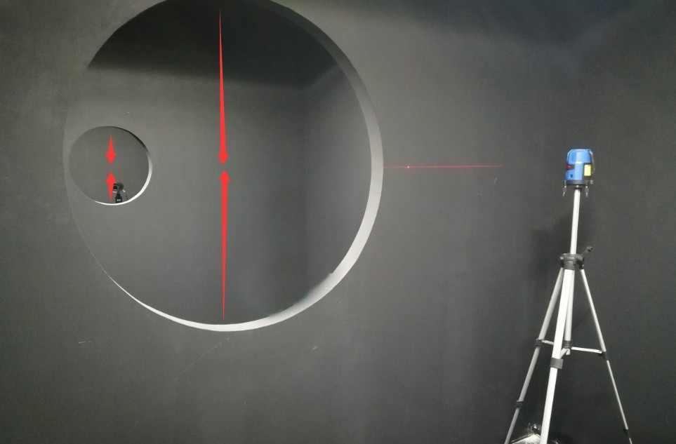
Figura 34
Notă: Nu așezați obiecte pe Goniofotometru sau în raza sa de rotație pentru a preveni deteriorarea echipamentului în timpul rotației.
Deschideți software-ul.
| Număr | notițe |
| ① | Faceți clic pentru a schimba modurile de unghi |
| ② | Faceți clic pe ① pentru a afișa unghiul C-Gamma aici în loc de unghiul B-Beta. |
| ③ | Apoi faceți clic pentru a deschide interfața de control al unghiului |
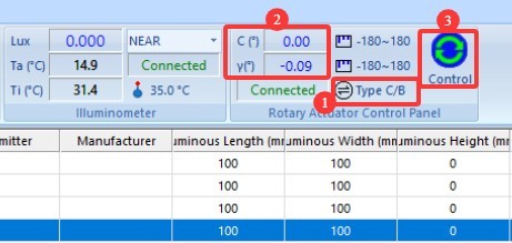
Figura 35
Click the continuous rotation button for any direction. The Gamma axis of the Goniophotomoeter will then begin to rotate continuously.
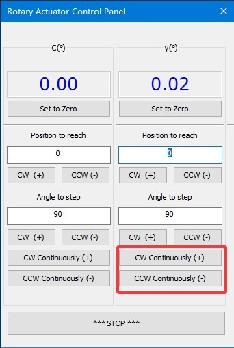
Figura 36
În acest moment, observați fasciculele laser orizontale emise de laserele cu o singură linie și cu linie încrucișată de pe axa principală a Goniofotometrului.
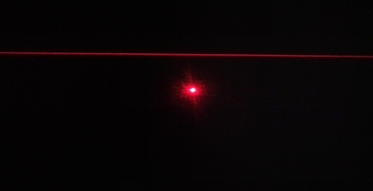
Figura 37
Apoi, folosind o cheie adecvată, ridicați goniofotometrul și nivelați-l ajustând înălțimea celor patru picioare ale sale. Rezultatul final al calibrării: Indiferent de unghiul gamma al goniofotometrului, fasciculul său laser drept se aliniază perfect cu fasciculul laser orizontal, așa cum se arată în figura de mai jos.
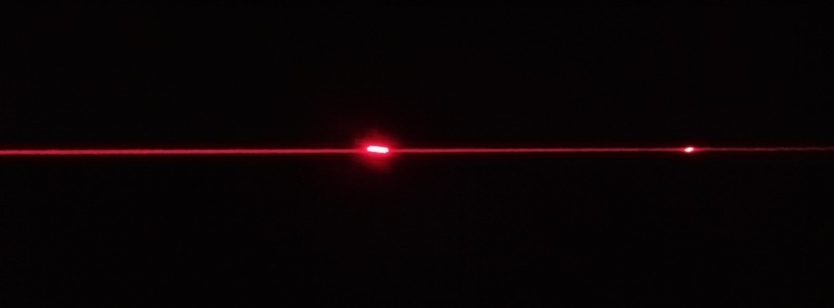
Figura 38
You’ll need plenty of patience to complete this step. Once adjusted, make sure all four legs of the main unit are firmly on the ground. Then click the “Stop” button on the software’s angle control interface to stop the Goniophotomoeter from rotating. Next, lock the four legs of the Goniophotomoeter in place using the screws at the top. Once the position and level of the Goniophotomoeter main unit have been properly adjusted, do not move it again, as this will cause deviations in the test results.
5.2 Calibrarea sondei fotometrice
5.2.1 Calibrarea sondei fotometrice la poziția de 0 grade
| Număr | notițe |
| ① | Introduceți 0 |
| ② | Faceți clic în orice direcție de rotație pentru a roti axa Gamma înapoi la poziția de 0 grade. |
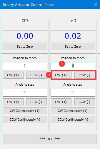
Figura 39
Verify that the single-line laser beam is passing through the exact horizontal center of the last partition at this point.
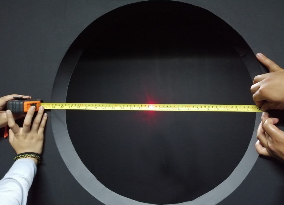
Figura 40
If not, follow the steps below.
| Număr | notițe |
| ① | Introduceți aici o valoare mică pentru unghi, în funcție de situația reală, cum ar fi 1, 0.1, 0.05 etc. |
| ② | Select a rotation direction and rotate the Gamma axis until the single-line laser passes through the exact center of the last partition horizontally. |
| ③ | Click “Set to 0 Degrees” to set the current position of the Gamma axis on the near-field luminance probe to 0 degrees. The password is LISUNGRUP. |
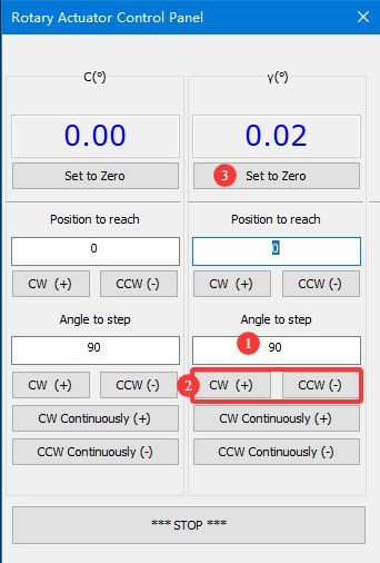
Figura 40.1
Note 1: After setting the Gamma axis of the near-field photometer to 0 degrees, do not arbitrarily set it to 0 degrees again, as this will cause deviations in the test results.
Note 2: Definition of the Gamma angle for a goniophotomoeter. The direction directly facing the photometer probe is defined as 0 degrees/360 degrees. When rotating clockwise, the angle value increases from 0 degrees to 360 degrees; when rotating counterclockwise, the angle value decreases from 360 degrees to 0 degrees. Since angle notation may vary, -90 degrees and 270 degrees correspond to the same position.
5.2.2 Montarea sondei fotometrice
Rotate the light sensor’s lens cover counterclockwise and remove it.
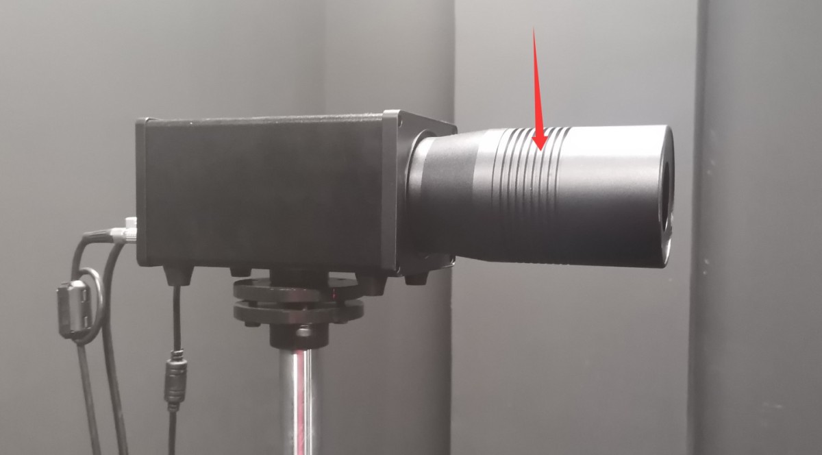
Figura 41
Cutia standard a lămpii conține o oglindă mică.
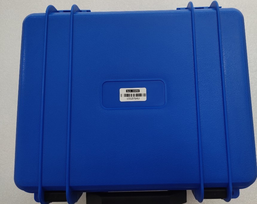
Figura 42
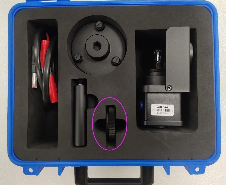
Figura 43
Scoateți reflectorul mic și atașați-l la sondă.
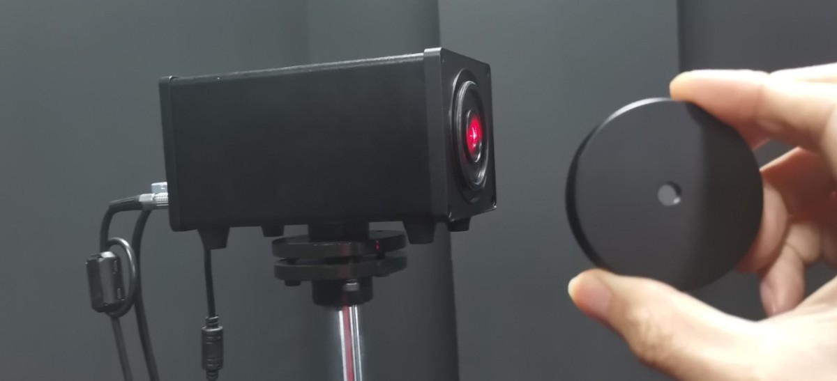
Figura 44
At this point, the Gamma axis of the near-field photometer is still at the 0-degree position. Slightly move the probe base and adjust the screws at points ① and ② to adjust the probe’s height and orientation. Position the probe so that the straight laser beam coming from the main axis hits the exact center of the mirror, and ensure that the reflected beam travels back along the same path.
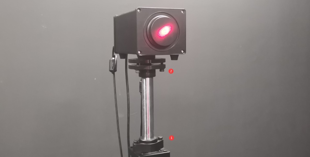
Figura 45
Apoi fixați baza suportului sondei pe podea cu șuruburi.
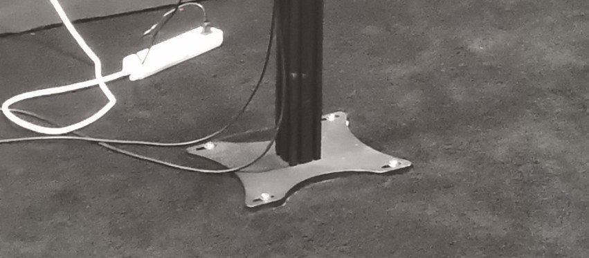
Figura 46
Once secured, you may need to make slight adjustments to the probe’s height and orientation so that the straight laser beam continues to hit the exact center of the reflector and the reflected beam returns along the same path. After calibration is complete, ensure that all screws are tightened. Then remove the reflector and reinstall the light probe’s light shield.
Note: Once the probe’s position and orientation have been set, do not adjust them, as doing so may cause the test data to be inaccurate.
You can secure the photometer probe’s power adapter to the probe mount as shown in the figure below to protect the probe’s power jack.
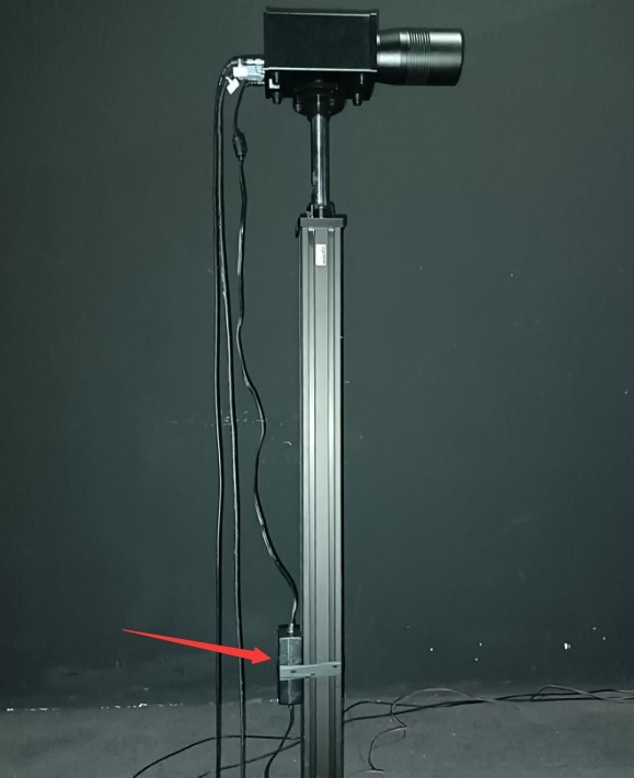
Figura 47
5.3 Cross-Line Laser Installation
Finally, the crosshair laser must be mounted on the side wall of the darkroom. Depending on the specific layout of each darkroom, the crosshair laser can be mounted on either the left or right wall. Take the darkroom layout shown in the figure below as an example.
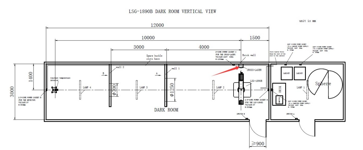
Figura 52
Go to the angle control screen.
| Număr | notițe |
| ① | Enter 90 (if the installation position of the crosshair laser in your darkroom blueprint is different, enter -90) |
| ② | Click to rotate the gamma axis to a 90-degree position, so that the main-axis laser is directly aligned with the position where the crosshair laser is installed. |
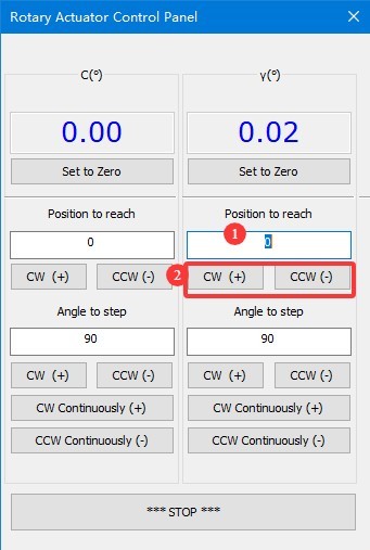
Figura 53
Fixați reticulul laser pe suportul triunghiular pe care îl furnizăm.
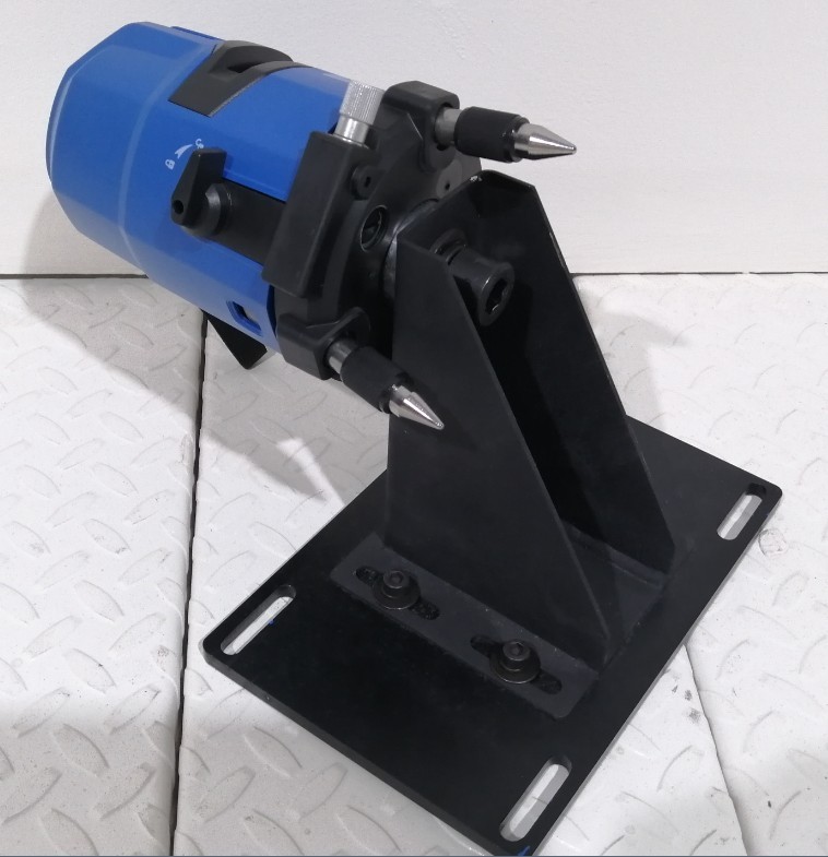
Figura 54
Porniți reticulul laser și utilizați direcția laserului cu o singură linie pentru a determina aproximativ poziția reticulului laser.
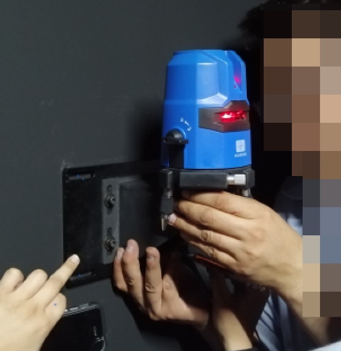
Figura 55
Fine-Tune the Position of the Crosshair Laser: The centerline of the straight laser should be perfectly aligned with the centerline of the crosshair laser. You can verify and adjust the position using the following method. Place a sheet of white paper at the exit of the cross-shaped laser and at the exit of the single-line laser. If the centerline of the single-line laser aligns with the centerline of the cross-shaped laser at both locations, you can confirm that the position and orientation of the cross-shaped laser are correct.
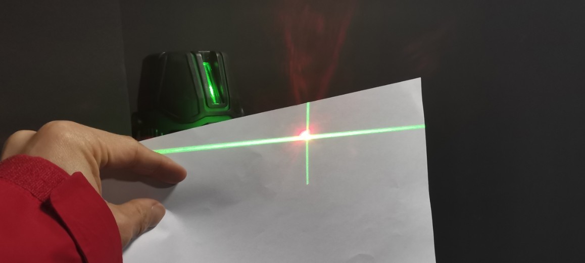
Figura 56
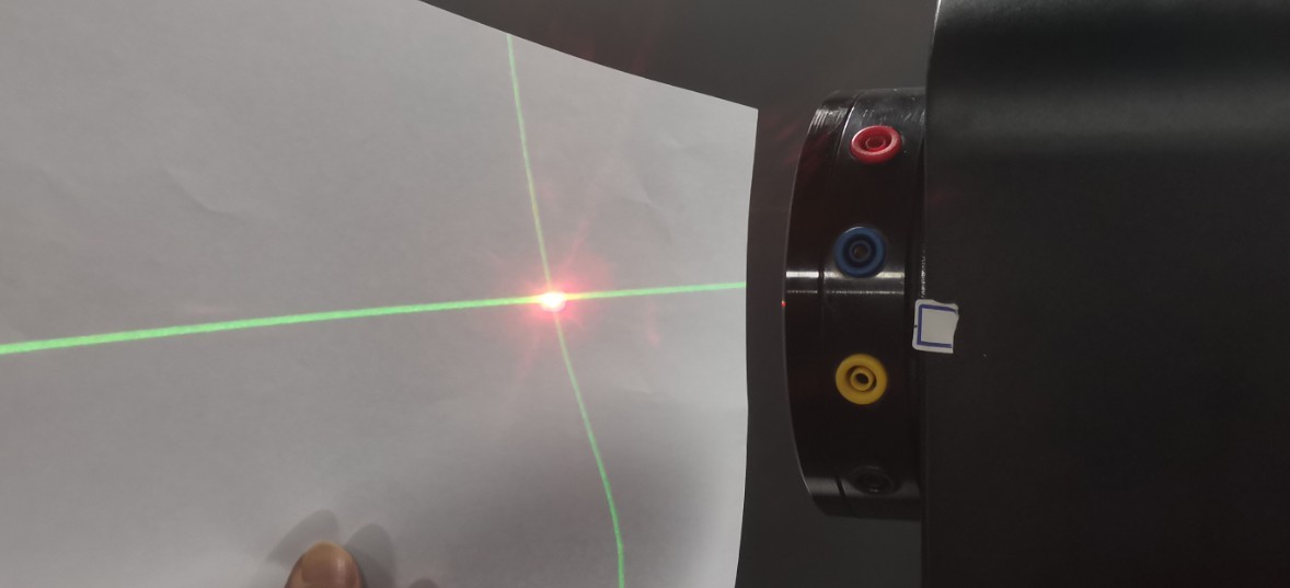
Figura 57
Next, secure the cross-laser tripod to the wall using screws. Once secured, you can still loosen the screws if necessary to make slight adjustments to the cross-laser in both the horizontal and vertical directions, ensuring it remains properly aligned. After calibration is complete, all screws should be tightened securely.
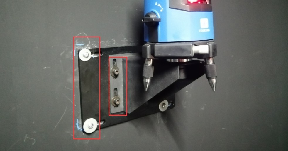
Figura 58
Then rotate the Gamma axis back to the 0-degree position. The cross-shaped laser beam is projected onto the opposite wall. You can use this to create a permanent mark. That is, when the cross-shaped laser beam is projected in this direction, it indicates the horizontal and vertical center positions of the Goniophotomoeter. This mark is needed for both calibration and testing.
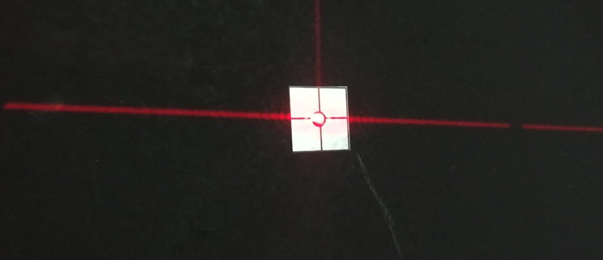
Figura 59
Installation and commissioning are complete. Turn off the line laser on the main shaft of the Goniophotomoeter.
5.4 Curățarea
You may shut down all equipment. When doing so, first turn off the power switch on each individual device, and then turn off the main power switch for the cabinet. Next, thoroughly clean the darkroom and control room. To prevent dust from entering the equipment, cover the devices with dust-proof cloths before cleaning. After cleaning, turn all equipment back on and continue with the calibration and testing procedures.
Notă: Păstrați camera obscură cât mai lipsită de praf în timpul utilizării.
6. Calibrarea
6.1 Instalarea și punerea în funcțiune a lămpilor standard
6.1.1 Instalarea lămpilor standard
First, turn on the crosshair laser on the wall and rotate it to ensure that it is aimed at the mark on the opposite wall.
Deschideți cutia lămpii standard.
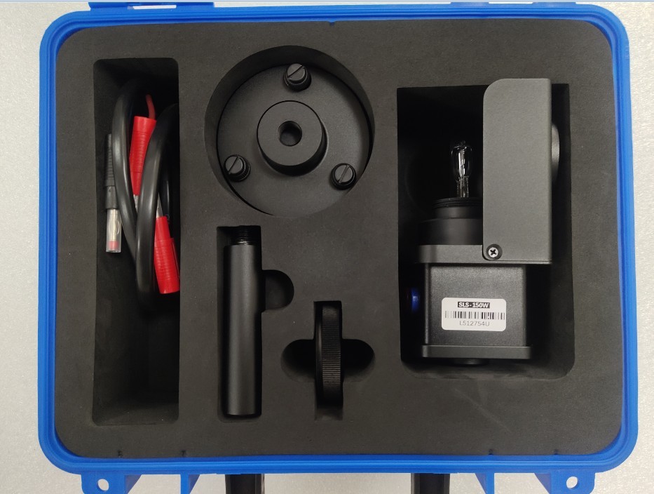
Figura 60
Apoi asamblați suportul standard al lămpii așa cum se arată în figura de mai jos.
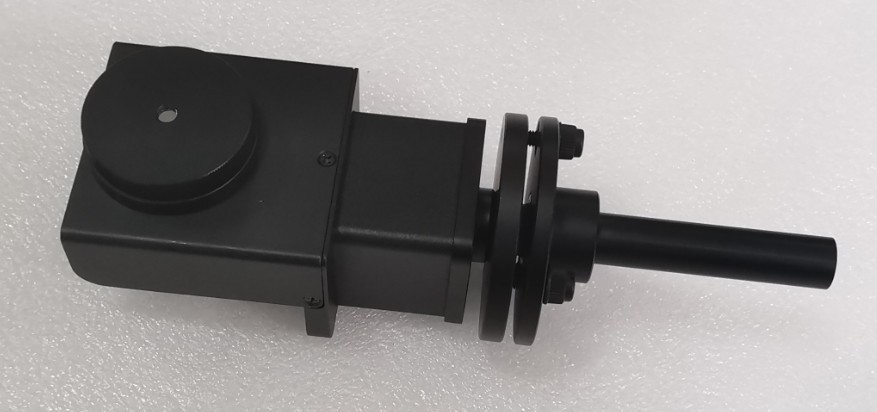
Figura 61
The main shaft of the Goniophotomoeter should still be aligned with the photometric probe, i.e., the probe’s 0-degree position. Locate the calibration rod and install it at the center of the Goniophotomoeter. Then remove the top section.
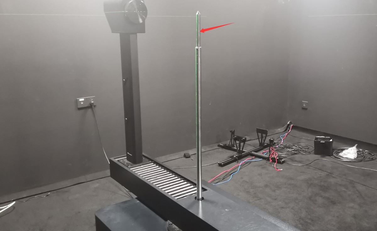
Figura 62
Vă rugăm să urmați instrucțiunile de mai jos pentru a conecta firele.
| Număr | notițe |
| ① | The main shaft of the goniophotomoeter has four terminals for connecting the power cables and sampling cables of the standard lamp and sample luminaire. Use short wires to bridge the red and yellow terminals together, and the black and blue terminals together. |
| ② | Connect the power cord of the standard lamp/sample fixture to the red and blue terminals on the main shaft. |
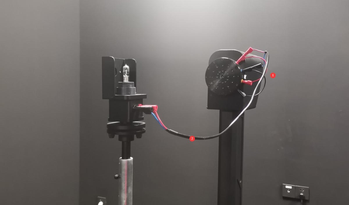
Figura 63
6.1.2 Calibration of the Standard Light Direction
| Număr | notițe |
| ① | Slăbiți șurubul de aici pentru a regla înălțimea lămpii standard. |
| ② | There are three screws here that allow you to adjust the pitch of the standard lamp. |
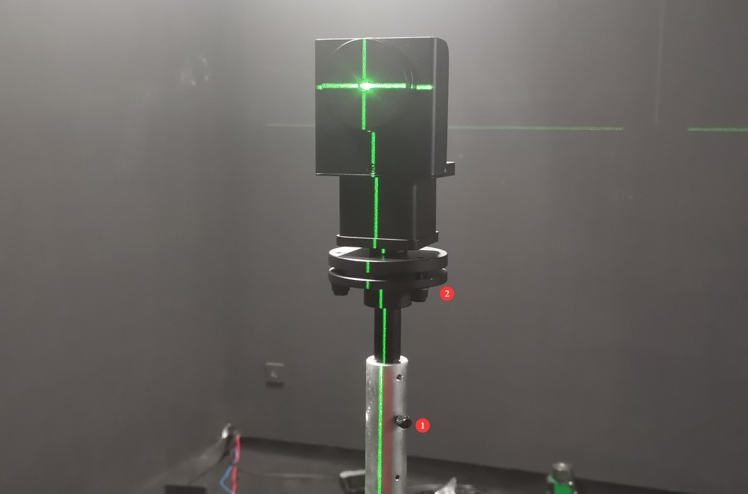
Figura 64
Lampa standard trebuie reglată astfel încât fasciculul laser în formă de cruce să fie îndreptat spre centrul oglinzii mici, iar fasciculele laser orizontale și verticale reflectate de oglindă să coincidă exact cu fasciculul laser original în formă de cruce.
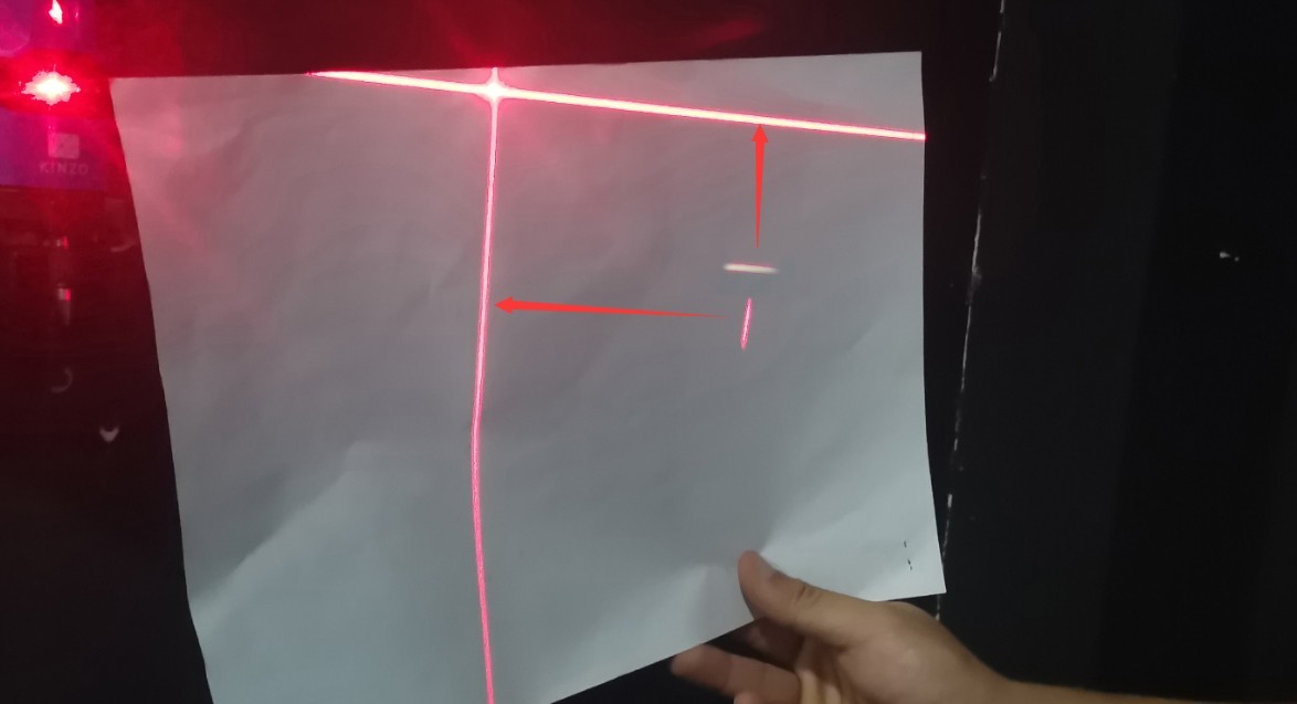
Figura 65
Based on our experience, follow these steps for calibration: First, adjust the height of the standard lamp to the appropriate position. The vertical reflected laser can be calibrated by rotating the calibration target, while the horizontal reflected laser can be calibrated by adjusting the pitch of the standard lamp. After calibration, the center height of the standard lamp may change, requiring you to readjust its height. Continue the reflection adjustment until the cross-shaped laser beam is projected onto the center of the small mirror, and the reflected horizontal and vertical laser beams perfectly align with the original cross-shaped laser beam.
Once the standard lamp is properly aligned, carefully remove the small reflector, taking care not to alter the alignment of the standard lamp during removal. Then turn off the cross-line laser.
6.2 Calibrarea sondei fotometrice
All standard lamps are constant-current DC light sources. Set the cabinet’s AC/DC switch to DC.
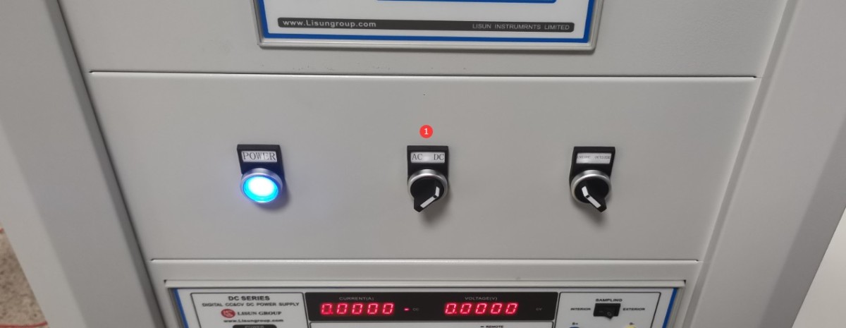
Figura 66
Deschideți controlerul software de unghi.
| Număr | notițe |
| ① | Introduceți -90 |
| ② | Click to rotate the Gamma axis to the -90-degree position (if the crosshair laser is installed in a different position on your darkroom drawing, you will need to rotate it to the 90-degree position). |
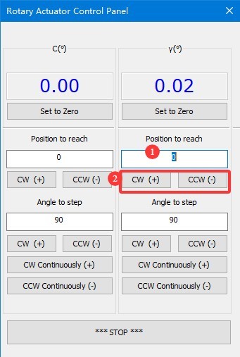
Figura 66.1
Aliniați orificiul rotund din suportul standard al lămpii astfel încât să fie orientat spre sonda fotometrică.
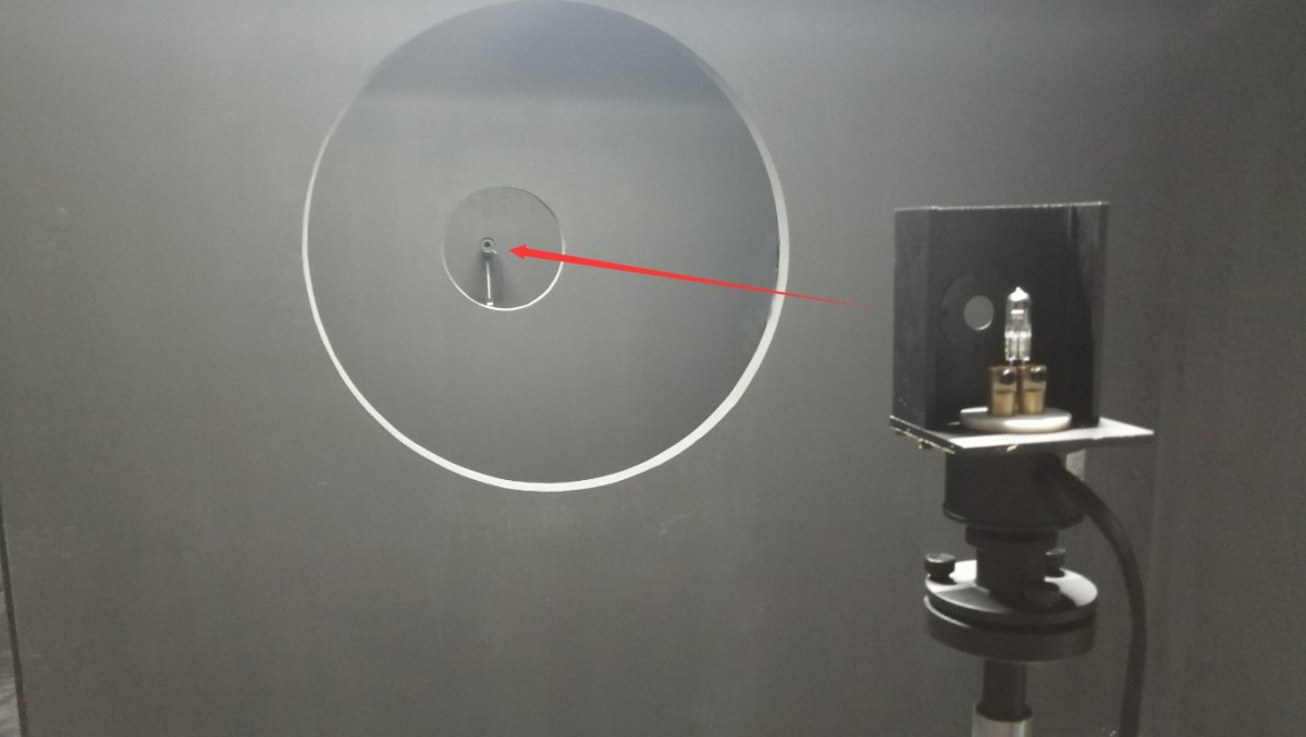
Figura 67
Turn on the calibration lamp and enter the calibration interface.
| Număr | notițe |
| ① | Selectați o sursă de alimentare CC |
| ② | Lampa standard este o sursă de lumină cu curent constant. Selectați CC (mod de curent constant) și introduceți tensiunea de referință și curentul nominal așa cum sunt specificate în certificatul lămpii standard; de obicei, acestea sunt 30 V și 6.1 A. |
| ③ | Faceți clic pentru a aprinde lampa standard și a stinge toate celelalte lumini din camera obscură. Lampa standard are nevoie de 15 minute pentru a atinge o stare stabilă. |
| ④ | După ce lampa standard s-a stabilizat, faceți clic pe pentru a accesa interfața de calibrare a fotometrului. |
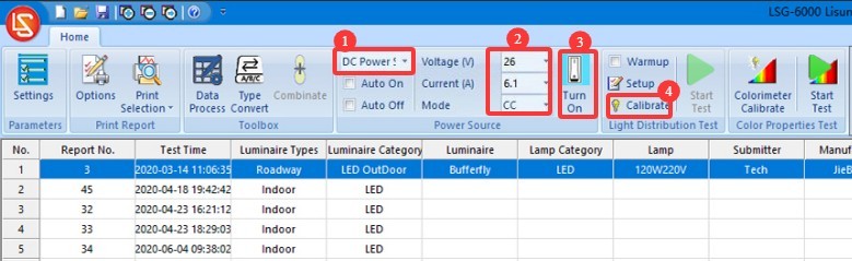
Figura 68
Închideți ușa camerei obscure și asigurați-vă că toate sursele de lumină din camera obscură sunt oprite, cu excepția lămpii standard.
| Număr | notițe |
| ① | Selectarea unei sonde fotometrice de câmp apropiat |
| ② | Calibrarea fluxului luminos — software-ul nostru include această opțiune, dar practicile standard actuale impun utilizarea calibrării intensității luminoase, iar lămpile standard incluse în configurația noastră standard sunt, de asemenea, lămpi standard de intensitate luminoasă. Prin urmare, nu este nevoie să se utilizeze calibrarea fluxului luminos în acest moment. |
| ③ | Metoda de calibrare a intensității luminii |
| ④ | Consultați certificatul de calibrare al lămpii standard și introduceți valoarea calibrată a intensității luminoase. |
| ⑤ | Faceți clic pentru a începe |
| ⑥ | Software-ul va calcula automat distanța de testare. |
| ⑦ | Pentru a verifica rezultatele, faceți clic pe „Verificare”, iar software-ul va afișa valoarea curentă a intensității luminoase măsurate. Valoarea intensității luminoase măsurate trebuie să corespundă cu valoarea calibrată a intensității luminoase. |
| ⑧ | Faceți clic pe „OK” pentru a salva și a ieși. |
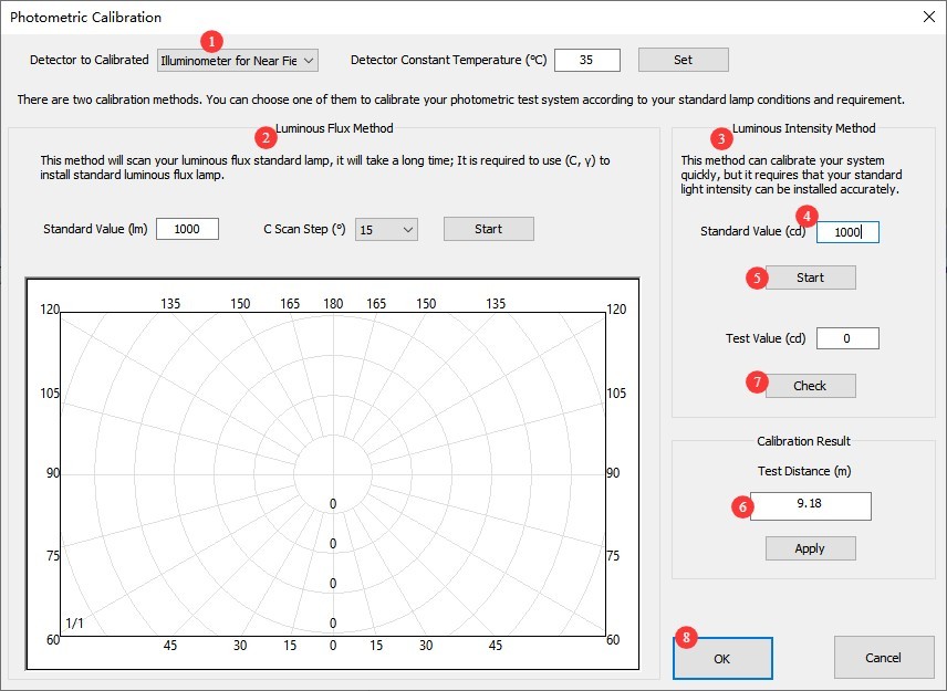
Figura 69
Note: The test distance is the distance from the center of the Goniophotomoeter to the surface of the photometric probe. The distance calculated by the software should be close to the actual distance; an error of 1% or less is considered normal. If the error is too large, please refer to Section 2.3.1 to verify that the darkroom is functioning properly, and refer to Chapter 5 to review the calibration steps.
După finalizarea calibrării, puteți opri lampa standard folosind software-ul. Deoarece lampa standard se încălzește destul de tare în timpul utilizării, așteptați să se răcească înainte de a o pune înapoi în ambalaj pentru depozitare în siguranță. Scoateți tija de calibrare și depozitați-o în siguranță.
6.3 Calibrare și întreținere
| Nicio modificare în camera obscură | Dacă nu au existat modificări la computer, recalibrarea nu este necesară. |
| No changes were made to the computer; simply unplug and replug the communication cable or reinstall the Goniophotomoeter software. No recalibration is necessary. | |
| If you switch to a new computer or reinstall the operating system, there is no need to recalibrate; simply enter the previous test distance and save it. | |
| Schimbări în camera obscură | Structura camerei obscure rămâne neschimbată; cu toate acestea, după o utilizare prelungită, vopseaua interioară se poate decolora sau exfolia. În funcție de cât de bine întrețineți camera obscură și de nivelul de precizie necesar pentru rezultatele testelor, puteți revopsi periodic camera obscură. După revopsire, camera obscură trebuie recalibrată. |
| A avut loc o modificare a configurației camerei obscure, așa că este necesară recalibrarea. |
7. Pregătiri înainte de testare
7.1 Selectarea și îmbătrânirea lămpii
Selectați corpuri de iluminat reprezentative pentru testare care respectă standardele naționale sau corporative; corpurile de iluminat noi trebuie să fie supuse unui tratament de îmbătrânire (pentru corpurile de iluminat cu LED, se recomandă o perioadă de îmbătrânire de 24 de ore);
Verificați dacă corpul de iluminat nu prezintă deteriorări vizibile, dacă cablajul intern este conectat corect și curățați orice pete de pe suprafața corpului de iluminat.
7.2 Introducere în modul de testare
Mod C-Gamma: Potrivit pentru majoritatea corpurilor de iluminat, cum ar fi iluminatul stradal, spoturile downlight, panourile de iluminat și lămpile pentru creșterea plantelor.
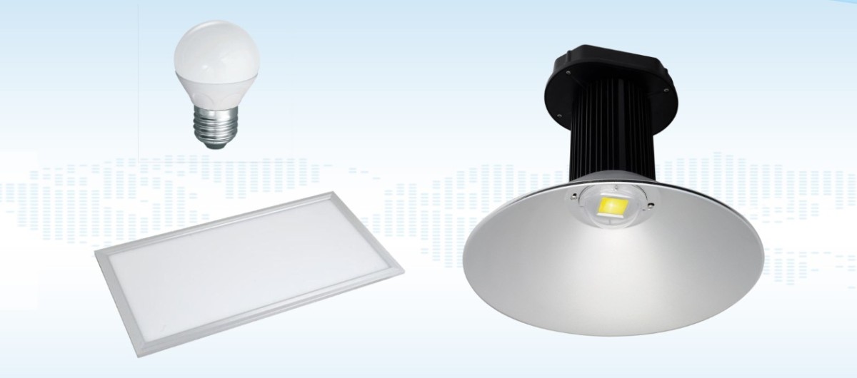
Figura 74
Mod Beta: Potrivit pentru spoturi, proiectoare și corpuri de iluminat similare; necesită instalarea unui braț auxiliar.
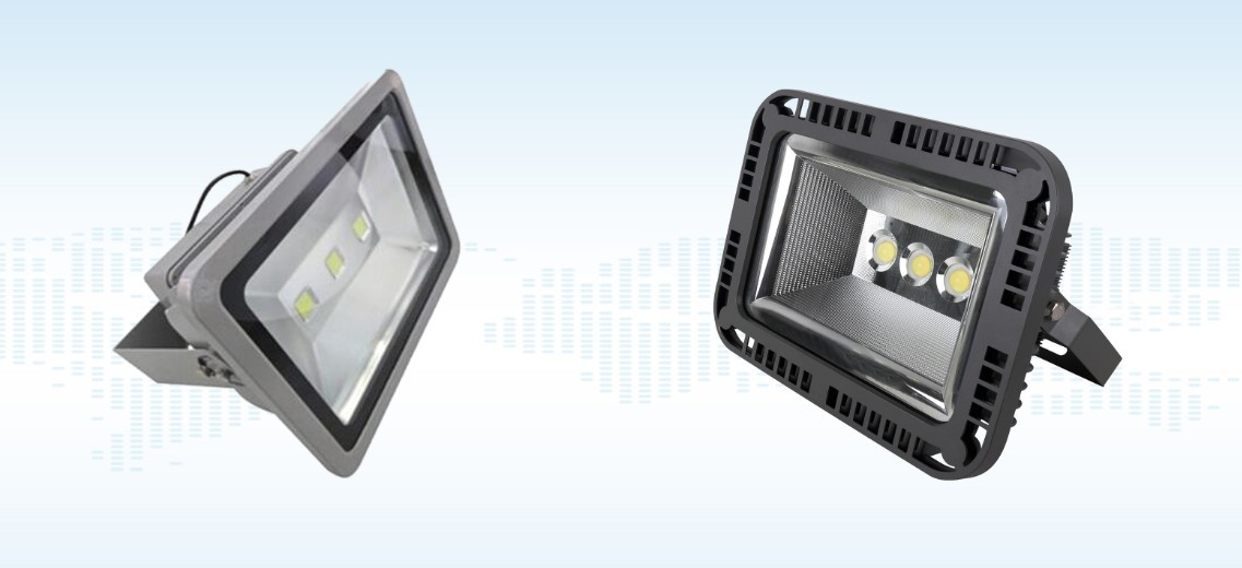
Figura 75
Mod Alpha: Potrivit pentru lumini auto și lumini de semnalizare.
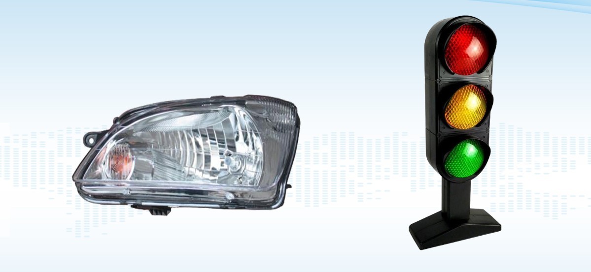
Figura 76
Nota: LSG-1890BCCD poate efectua teste C-Gamma și B-Beta. Pentru testarea A-Alfa, este necesar un goniofotometru de tip A; vă rugăm să ne contactați dacă este necesar.
8. Testul C-Gamma
8.1 Instalarea și aprinderea luminilor
8.1.1 Instalarea corpului de iluminat
Avem două dispozitive de testare C-Gamma; această procedură folosește ca exemplu dispozitivul de testare în formă de cruce.
| Număr | notițe |
| ① | Clemele mari în formă de cruce sunt utilizate pentru diverse tipuri de corpuri de iluminat |
| ② | Dispozitiv E27 pentru testarea becurilor glob |
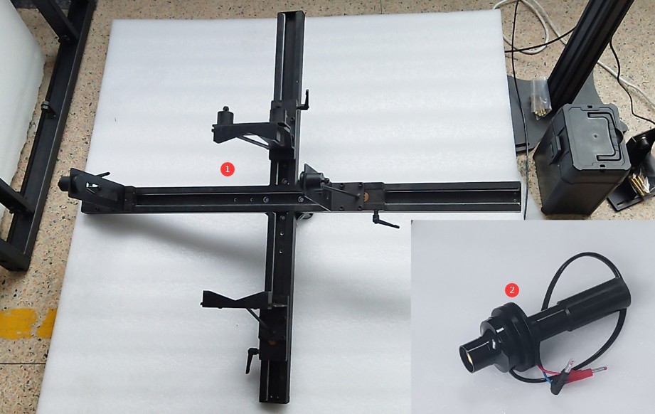
Figura 77
Attach the fixture to the Goniophotomoeter. Turn on the wall-mounted cross-line laser and verify that the cross-line laser is projected accurately onto the markings made on the opposite wall.
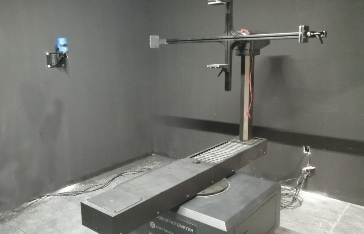
Figura 78
On the angle control interface, select the near-field photometric probe. Rotate the Gamma axis 90 degrees so that the crosshair laser points directly at the center of the crosshair fixture. Mount the lamp under test onto the crosshair fixture. Adjust the lamp’s position so that the crosshair laser is centered on the light-emitting surface of the lamp under test, and the light-emitting surface is parallel to the crosshair fixture.
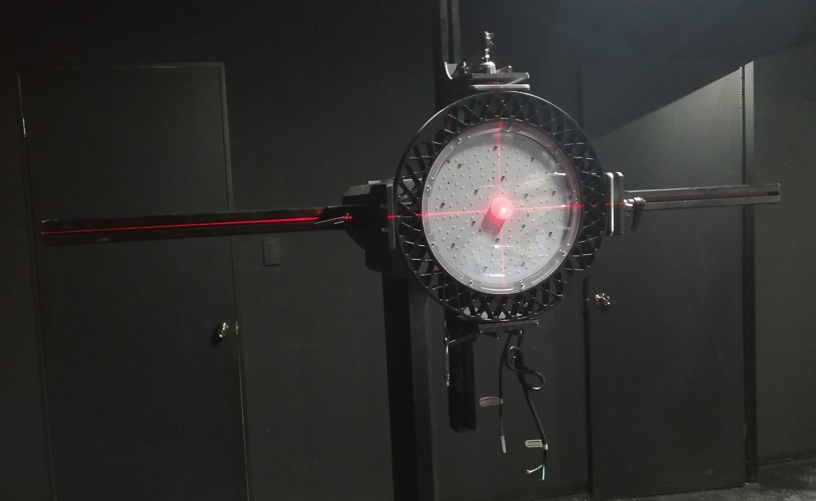
Figura 79
Then rotate the Gamma axis back to 0 degrees. Turn the dial here.
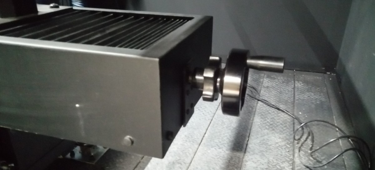
Figura 80
Align the light-emitting surface of the fixture with the vertical laser beam of the crosshair.
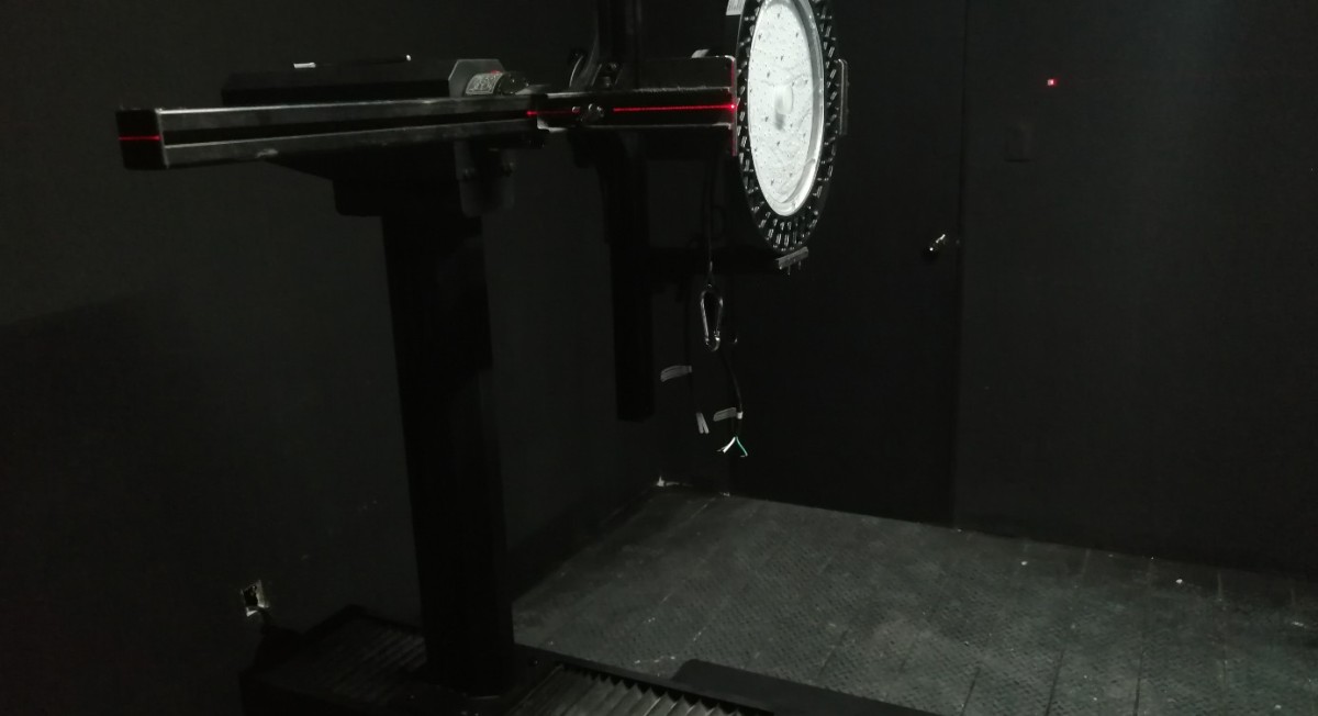
Figura 81
Caution is required when installing directional luminaires. When the angle of the C-plane on the Goniophotomoeter is 0 degrees, according to streetlight installation standards, the light pole should point directly upward, as shown in the figure below.
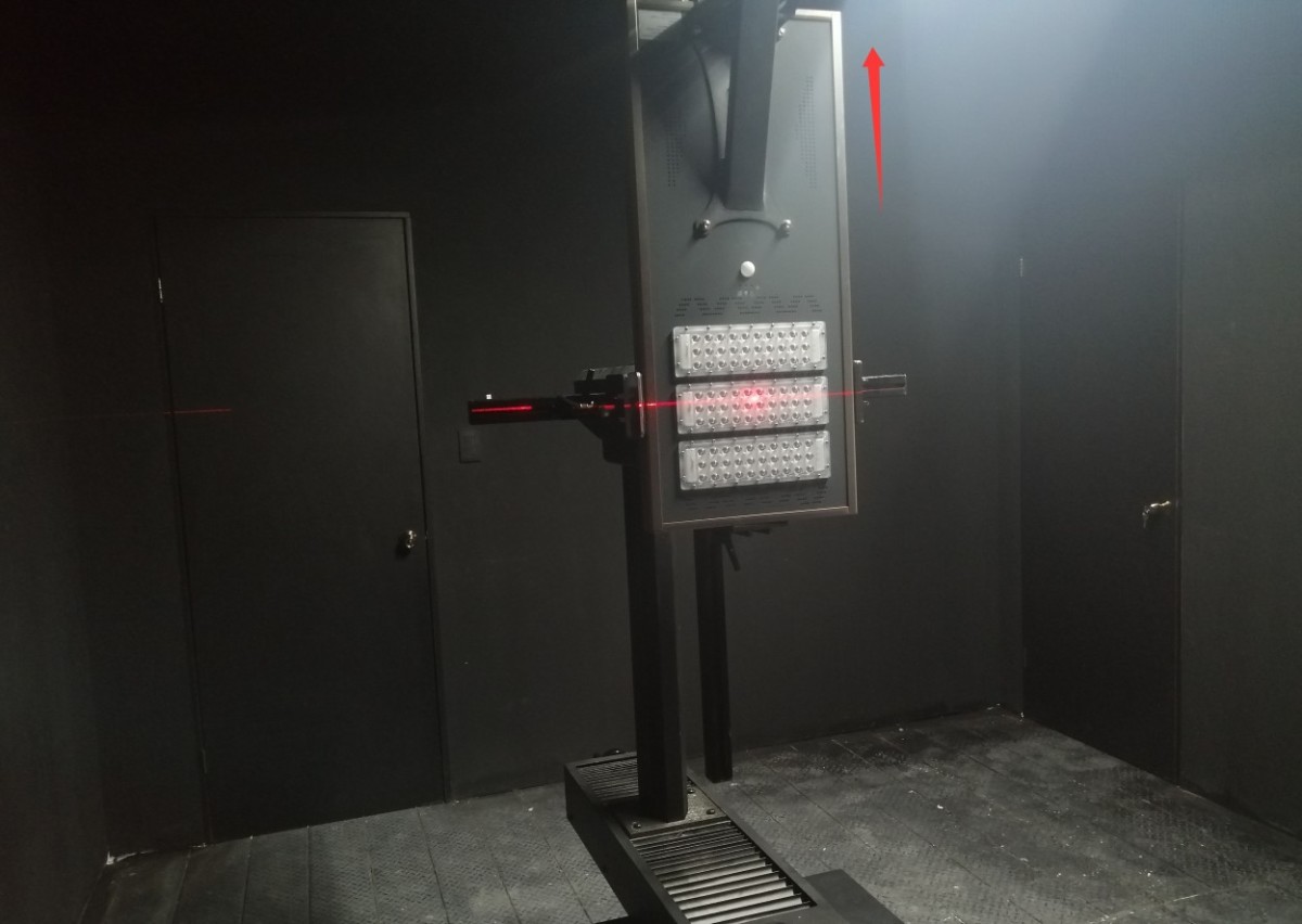
Figura 81.1
Când unghiul planului C de pe goniofotometru este de 0 grade, banda luminoasă trebuie instalată vertical, în conformitate cu standardele industriale, așa cum se arată în figura de mai jos.
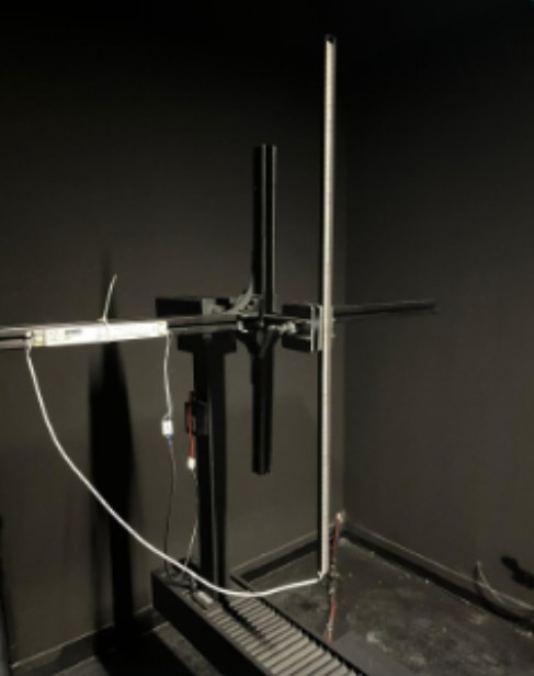
Figura 81.2
8.1.1 Aprinderea luminilor
Conectați cablul de alimentare la corpul de iluminat testat. Metoda de conectare pentru corpul de iluminat testat este aceeași ca și cea pentru corpul de iluminat standard; consultați Secțiunea 6.1.1.
Reglați întrerupătorul dulapului în funcție de parametrii corpului de iluminat testat.
| Număr | notițe |
| ① | If the sample luminaire is AC-powered, switch to the AC setting; if it is DC-powered, switch to the DC setting. |
| ② | Internal/External Sampling Switch for Electrical Parameters. External sampling uses a four-wire configuration and provides more accurate voltage readings. Unless otherwise specified, please set this switch to “External Sampling”; no further adjustments are necessary. |
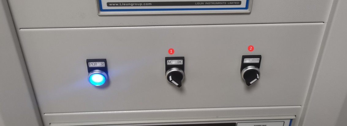
Figura 82
Dacă corpul de iluminat eșantion este alimentat de curent alternativ.
| Număr | notițe |
| ① | Selectați alimentarea cu curent alternativ |
| ② | Pe baza parametrilor eșantionului, introduceți tensiunea și frecvența corecte. |
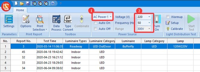
Figura 83
Dacă corpul de iluminat eșantion este alimentat cu curent continuu.
| Număr | notițe |
| ① | Selectați o sursă de alimentare CC |
| ② | Pe baza parametrilor eșantionului, introduceți tensiunea și curentul corecte. |
| ③ | Select the output mode: CC stands for constant current, and CV stands for constant voltage. If you select constant current, you need to enter the sample’s rated current value; for the voltage, simply enter the maximum output voltage of this DC power supply. If you select constant voltage, enter the sample’s rated voltage and the DC power supply’s maximum output current. Notă: Dacă modelul sursei de alimentare CC este DC3010Tensiunea maximă de ieșire este de 30V, iar curentul maxim de ieșire este de 10A. |
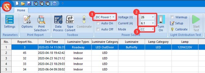
Figura 84
Software-ul oferă două metode pentru aprinderea și stingerea lămpii eșantion, iar utilizatorii pot alege între ele.
| Număr | notițe |
| ① | If you check the “Auto Turn On” and “Auto Turn Off” options, the software will automatically power on the sample according to the selected power source and the entered electrical parameters when the test begins, and will automatically cut off the sample’s power when the test ends. |
| ② | If the “Auto On” and “Auto Off” options are not checked, you can still click this button; the software will illuminate the sample based on the selected power source and the entered electrical parameters. Clicking this button again will cut off the power to the sample. |
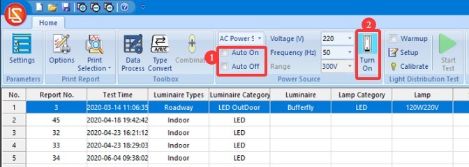
Figura 85
8.2 Setări parametri preîncălzire
| Număr | notițe |
| ① | Dacă bifați caseta „Preîncălzire”, software-ul va preîncălzi corpurile de iluminat conform parametrilor de preîncălzire specificați la începerea testului, iar testul va porni automat odată ce preîncălzirea este finalizată. If you do not check the “Preheat” box, the software will start the test immediately. |
| ② | Setările parametrilor de preîncălzire |
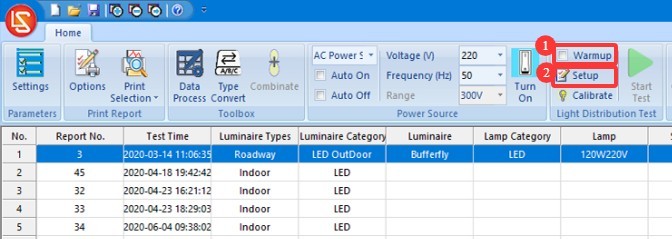
Figura 86
Faceți clic pe „Setări parametri preîncălzire”.
| Număr | notițe |
| ① | Warm-up Duration Setting: The purpose of the warm-up is to allow the light fixture to remain on for a period of time until its luminous and color parameters stabilize, after which the test proceeds automatically. |
| ② | Sampling interval: The software automatically samples data at the set interval throughout the entire warm-up period to obtain real-time data. We recommend setting this to 5 seconds or longer. |
| ③ | If checked, the test will automatically skip the remaining warm-up time and proceed once the light fixture has reached a stable state; if unchecked, the test will begin only after the warm-up period has been completed according to the set duration. |
| ④ | Definition of a luminaire’s steady-state condition. If the values are set to 20 and 0.5%, the luminaire is considered to be in a steady state if the parameter has not varied by more than 0.5% over the past 20 minutes. |
| ⑤ | Puteți selecta parametrii pe care software-ul să îi utilizeze pentru a determina dacă un corp de iluminat este stabil: parametri optici, parametri electrici |
| ⑥ | Software-ul va salva curbele de modificare pentru parametrii selectați în timpul perioadei de încălzire în raportul de testare. |
| ⑦ | După ce ați terminat de configurat setările, faceți clic pe OK pentru a salva și a ieși. |
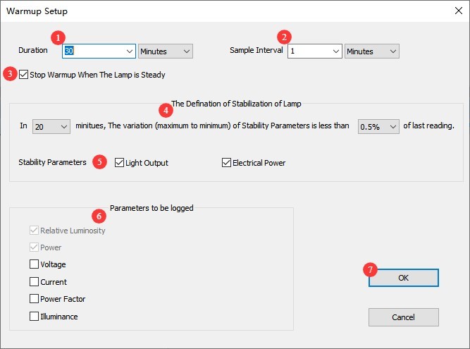
Figura 87
8.3 Configurarea parametrilor de testare și pornirea testului
Faceți clic pe „Începeți testul”.
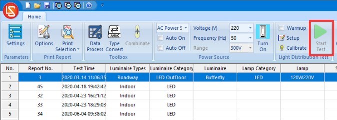
Figura 88
Accesați ecranul de setări ale parametrilor de testare.
| Număr | notițe |
| ① | Tipuri de corpuri de iluminat: lumini de interior, lumini de exterior sau lumini pentru creșterea plantelor - aceste trei tipuri de corpuri de iluminat sunt supuse testării C-Gamma. |
| ② | Select whether the luminaire is symmetrical or asymmetrical. Unless there are specific requirements, select the first option (asymmetrical) regardless of whether the luminaire being tested is symmetrical or not (to obtain the luminaire’s actual data). |
| ③ | Interval unghi plan C: Selectați între 0 și 180 de grade; nu este necesară nicio modificare. Pentru date cuprinse între 180 și 360 de grade, software-ul va converti automat C-plane angle intervals. Symmetrical luminaires, such as indoor lights, can use a larger interval (e.g., 30 degrees), while asymmetrical luminaires, such as streetlights, can use a smaller interval (e.g., 10 degrees). The smaller the angle interval, the higher the test accuracy, but the longer the test will take. If time permits, we recommend selecting a smaller angle interval. |
| ④ | Gamma plane angle range: If the sample’s light irradiation angle exceeds 180 degrees (e.g., incandescent bulbs), select -180 degrees to 180 degrees; if the sample’s light irradiation angle is less than 180 degrees (e.g., panel lights), you may select a Gamma plane angle interval ranging from -90 degrees to 90 degrees. Unless there are special requirements, a 1-degree interval is sufficient. The specific angle interval selected here has no effect on test speed. |
| ⑤ | Dacă sistemul are mai multe sonde fotometrice, vă rugăm să o selectați pe cea pe care doriți să o utilizați. |
| ⑥ | For standard luminaires undergoing standard testing, select “Normal Speed”; if the luminaire being tested has an extremely narrow beam angle, select “Slow Speed” to obtain more accurate test results; for expedited testing, select “Fast Speed.” |
| ⑦ | Fixed Range: If you are consistently measuring the same type of light fixture and the luminous intensity data does not vary significantly, you can check this box to save time. If you have ample time, or if you frequently test lamps with different luminous intensities, we recommend leaving this box unchecked; in this case, the photometric probe will automatically select the appropriate range for each lamp and enter continuous scanning mode. This is suitable when the angular interval of the Gamma plane is between -180 degrees and 180 degrees. During the test, when the Gamma angle approaches ±180 degrees, simultaneously rotating the C-axis to the next scanning position—that is, the Gamma axis rotates continuously without stopping to save time. If you have ample time, we recommend leaving this option unchecked. |
| ⑧ | To set the monitoring angle during lamp warm-up, simply set it to (0, 0). |
| ⑨ | Normalizarea se referă la decizia de a aplica sau nu o valoare uniformă primului rând de date din tabelul de intensitate luminoasă al unui raport de testare; anumite standarde, cum ar fi standardul american pentru iluminatul stradal, pot solicita efectuarea unei ajustări similare. Există trei opțiuni: fără normalizare, normalizare la valoarea maximă (ceea ce va crește ușor fluxul luminos total al corpului de iluminat) și normalizare la valoarea medie (ceea ce lasă fluxul luminos în esență neschimbat). |
| ⑩ | If you need to remove all stray light outside a specific angle, check this box and enter the desired angle . For example, if you check this option and enter 60, the data outside ±60 degrees of the luminaire’s gamma plane will automatically be set to 0. |
| ⑪ | Enter the number of light sources in the luminaire and the rated luminous flux of each light source. If you do not know these values, you may leave them blank; this will not affect the test results. |
| 10 | Introduceți dimensiunile suprafeței emițătoare de lumină a eșantionului. Pentru corpurile de iluminat de interior, software-ul necesită aceste date pentru a calcula curba limită de luminanță, UGR și alți parametri. |
| 10 | Enter information about the sample light fixture |
| 10 | Enter the temperature and humidity of the test environment (i.e., the darkroom) |
| ⑮ | Faceți clic pe OK pentru a accesa ecranul de încălzire sau pentru a accesa ecranul de testare. |
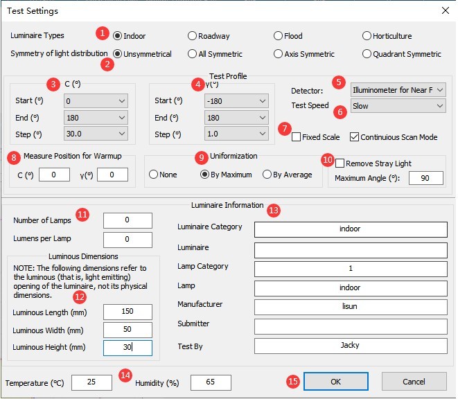
Figura 89
Then wait for the software testing to finish.
9. Testarea B-Beta
9.1 Install and Turn On the Lights
9.1.1 Instalarea corpurilor de iluminat
Porniți laserul reticular și asigurați-vă că acesta încă luminează marcajul pe care l-ați făcut pe peretele opus.
Găsiți dispozitivul de testare B-Beta pătrat.
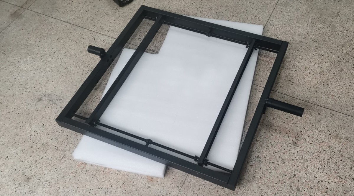
Figura 92
When performing the B-Beta test, reattach the Goniophotomoeter’s auxiliary arm. Then, install the B-Beta fixture vertically as shown in the figure.
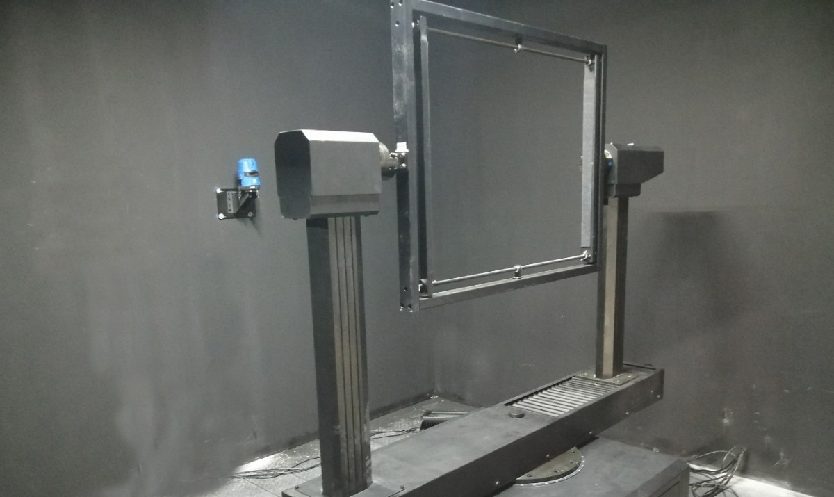
Figura 93
| Număr | notițe |
| ① | Click to switch to the angle display mode |
| ② | Faceți clic pe ① pentru a afișa unghiul B-Beta aici în loc de unghiul C-Gamma. |
| ③ | Faceți clic pentru a deschide interfața de control al unghiului |
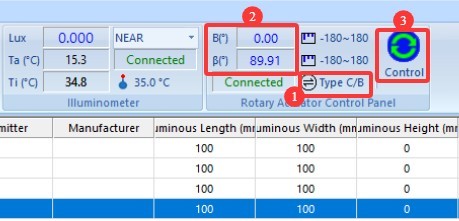
Figura 94
| Număr | notițe |
| ① | Când unghiul B este de 0 grade, dispozitivul de fixare trebuie să fie în poziție verticală; acest lucru poate fi verificat folosind o nivelă. |
| ② | Introduceți 0 |
| ③ | Faceți clic pentru a seta unghiul Beta la 0 grade. Notă: Poziția de 0 grade pentru unghiul Gamma nu este aceeași cu poziția de 0 grade pentru unghiul Beta. |
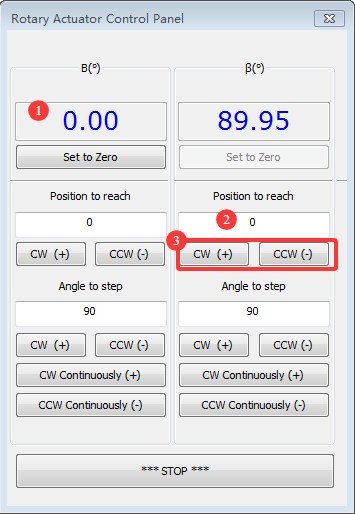
Figura 95
After rotating Beta to the 0-degree position, mount the floodlight onto the fixture, ensuring that the light-emitting surface of the floodlight faces the photometric probe. Adjust the mounting position of the fixture so that the cross-shaped vertical laser beam aligns with the light-emitting surface of the floodlight.
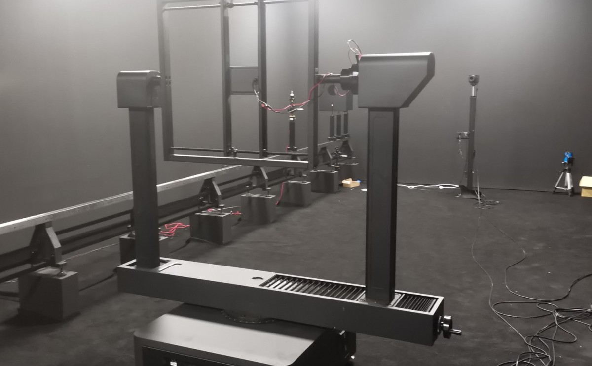
Figura 96
To ensure the sample is centered in the Goniophotomoeter, rotate the Beta fixture to the position shown in the figure below so that the sample’s light-emitting surface faces the crosshairs. Use the crosshairs to fine-tune the position of the sample holder.
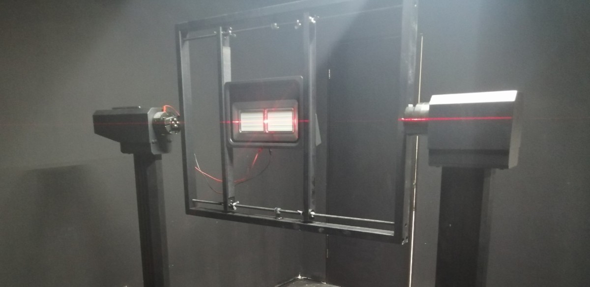
Figura 97
După ce corpul de iluminat este instalat, puteți opri reticulul laser.
9.1.2 Aprinderea luminilor
Vă rugăm să consultați 8.1.2.
9.2 Setări parametri preîncălzire
Vă rugăm să consultați Secțiunea 8.2.
9.3 Configurarea parametrilor de testare și pornirea testului
Faceți clic pe „Start Test” pentru a accesa ecranul de setări ale parametrilor de testare.
| Număr | notițe |
| ① | Selectați „Floodlight”, iar modul de testare va trece automat la B-Beta. |
| ② | Intervalul de unghi pentru Planul B este de la -90 de grade la 90 de grade. Nu este nevoie să ajustați the angle intervals for Plane B; you can select smaller angle intervals, such as 5 degrees or 10 degrees. The smaller the interval, the higher the test accuracy, but the longer it takes. |
| ③ | Intervalul unghiului planului Beta este de la -90 grade la 90 grade. Nu este nevoie să ajustați Beta plane interval angle; unless there are special requirements, select 1 degree. Different interval angles here have no effect on test speed. |
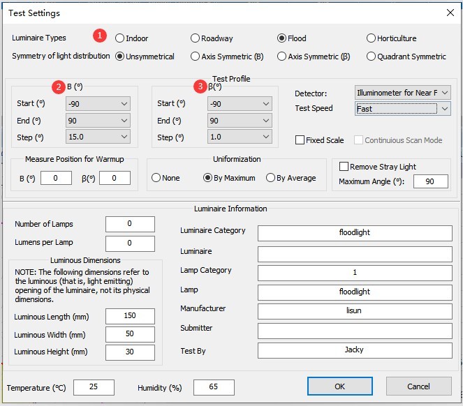
Figura 98
For other parameter settings, refer to Section 8.1.3. Once you have configured the settings, click “Start” and wait for the software to complete the test.
10. Prelucrarea rapoartelor de testare
10.1 Organizarea fișierelor bazei de date
| Număr | notițe |
| ① | În mod implicit, toate rapoartele de testare sunt stocate automat în fișierul bazei de date deschise în prezent, în ordinea în care au fost executate testele. |
| ② | Pentru a șterge un raport, selectați-l și apoi faceți clic pe „Șterge”. |
| ③ | To make it easier to find test reports, click the blank button shown in the image below to create a new database file, and store reports for different lighting fixtures in separate database files. After creating a new database file, you can proceed directly with testing without having to recalibrate or reconfigure the system. |
| ④ | Faceți clic pe „Deschidere” pentru a vizualiza rapoartele de testare din alte fișiere ale bazei de date. |
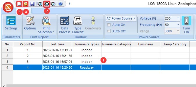
Figura 100
Note 1: The next time the software is launched, it will automatically load the database file used during the previous session. If the path to that database file has changed or its name has been modified, the software will prompt you to create a new database file.
Nota 2: Evitați plasarea fișierelor bazei de date pe desktopul computerului ori de câte ori este posibil.
10.2 Setări de afișare a raportului de testare
| Număr | notițe |
| ① | Puteți face dublu clic pentru a încărca o imagine a corpului de iluminat. |
| ② | Puteți face dublu clic pe conținutul afișat în această zonă pentru a-l edita. |
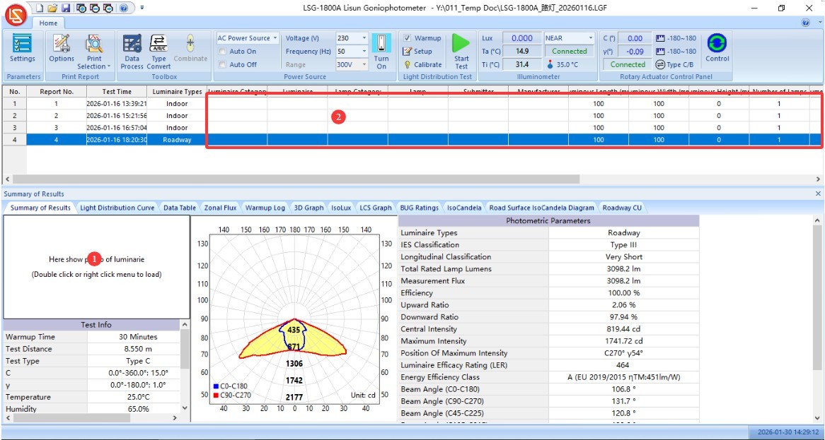
Figura 101
| Număr | notițe |
| ① | Faceți clic pe „Setări” |
| ② | Pentru selectarea unității, se folosește în general „cd”; cu toate acestea, unele standarde mai vechi - cum ar fi cele privind becurile economice - pot necesita utilizarea „cd/klm”. |
| ③ | Setarea unghiului de iluminare C0 pentru iluminatul stradal. Standardele CIE/GB și IESNA au cerințe inconsistente; vă rugăm să selectați standardul pe care îl urmați. |
| ④ | Personalizați unghiul de divergență. Software-ul afișează automat unghiul de jumătate de vârf (denumit în mod obișnuit unghiul fasciculului, calculat ca 50% din intensitatea luminoasă maximă) și unghiul efectiv al fasciculului (calculat ca 10% din intensitatea luminoasă maximă). Dacă doriți să personalizați unghiul de divergență, introduceți procentul intensității maxime a luminii și bifați caseta (de exemplu, 0.25 pentru 25%). În acest caz, raportul de testare va afișa nu numai unghiul de jumătate de vârf și unghiul efectiv al fasciculului, ci și unghiul de divergență personalizat. |
| ⑤ | Bifați această casetă pentru a afișa unghiul conului de intensitate luminoasă maximă în raport. |
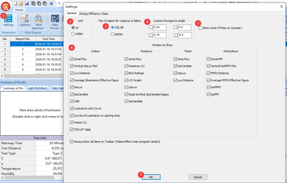
Figura 102
| Număr | notițe |
| ① | Comutați la ecranul de setări „Eficiență energetică”, apoi selectați standardul și tipul de corp de iluminat aplicabile. |
| ② | Faceți clic pentru a aplica raportului de testare curent |
| ③ | Faceți clic pe OK pentru a salva și a ieși. |
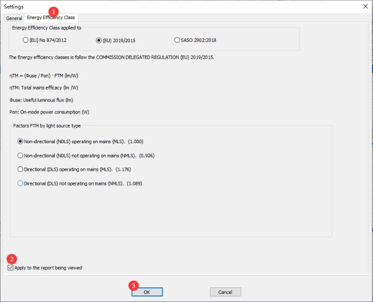
Figura 103
Each display window has several settings that allow you to customize the display. Users can experiment with adjusting these settings to achieve their desired display effects.
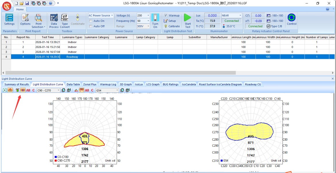
Figura 103.1
10.3 Prelucrarea datelor de testare
10.3.1 Double-sided luminaires
Pentru lămpile care emit lumină din ambele părți, utilizați modul de testare a lămpii de interior pentru a testa fiecare parte individual — adică, setați intervalul unghiului planului gamma la -90 de grade până la 90 de grade în timpul testării — și apoi generați două rapoarte de testare.
| Număr | notițe |
| ① | Țineți apăsată tasta „Ctrl” de pe tastatura computerului, apoi faceți clic pentru a selecta cele două rapoarte de testare pe care tocmai le-ați primit. |
| ② | Faceți clic pe „Sinteza datelor” în bara de navigare a software-ului |
| ③ | În fereastra pop-up, puteți face clic pentru a comuta între fasciculele de lumină ascendente și descendente. |
| ④ | Selectați „Compozit” |
| ⑤ | Faceți clic pe OK pentru a salva și a ieși |
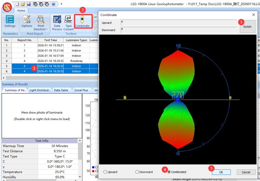
Figura 104
Aceasta va genera un nou raport de testare sintetică, așa cum se arată în figura de mai jos.
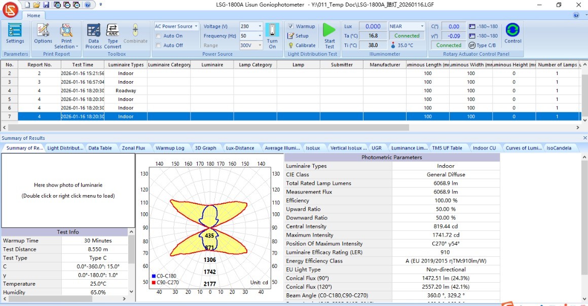
Figura 105
10.3.2 Conversia tipurilor de rapoarte de testare
| Număr | notițe |
| ① | Faceți clic pe „Conversie tip” |
| ② | Rapoartele de testare pot fi convertite între patru tipuri |
| ③ | When converting to a C-Gamma test report, you can use the “termination angle” of the C-plane to generate a symmetric test report. If the termination angle is set to 360 degrees, there is no symmetry; if the termination angle is set to 180 degrees, the report can be converted to an axially symmetric test report; if the termination angle is set to 90 degrees, the report can be converted to a quadrant-symmetric test report; if the termination angle is set to 0 degrees, the report can be converted to a fully symmetric test report. This feature is primarily intended for symmetric indoor lighting fixtures; certain lighting design software programs, such as DIALUX, may require you to use this setting when importing fully symmetric IES files. |
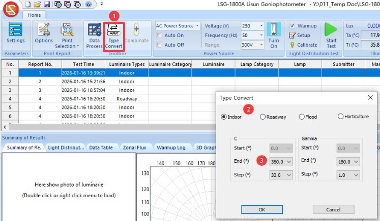
Figura 106
10.4 Exportul datelor de testare și imprimarea rapoartelor de testare
10.4.1 Exportarea datelor de testare
| Număr | notițe |
| ① | Faceți clic pe sigla roșie din colțul din stânga sus al software-ului |
| ② | Faceți clic pe „Exportați date” în meniul derulant |
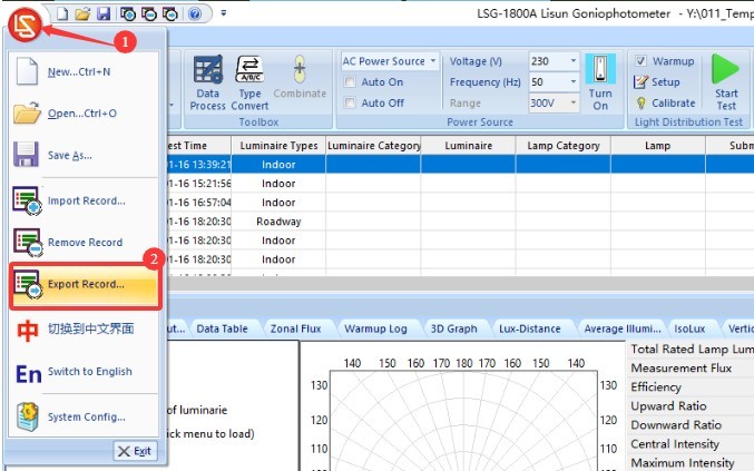
Figura 107
Fișierele pot fi exportate într-o varietate de formate standard.
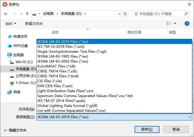
Figura 108
10.4.2 Imprimarea rapoartelor de testare
Setări de imprimare.
| Număr | notițe |
| ① | Faceți clic pentru a deschide ecranul „Setări de imprimare” |
| ② | Raportul afișează opțiuni de limbă; puteți alege între chineză și engleză. |
| ③ | Formatul numărului paginii |
| ④ | Informații despre antetul raportului |
| ⑤ | Titluri de raport în chineză și engleză |
| ⑥ | General Report Content—Applicable to Reports on All Types of Lighting Fixtures |
| ⑦ | Întrucât luminile interioare, iluminatul stradal, proiectoarele și lămpile pentru creșterea plantelor au parametri cheie diferiți, conținutul raportului va varia în consecință. Puteți selecta elementele specifice pe care doriți să le includeți în raport. |
| ⑧ | Opțiuni TM-30 |
| ⑨ | CIE color space diagram or SDCM color tolerance diagram—you can choose only one of them. |
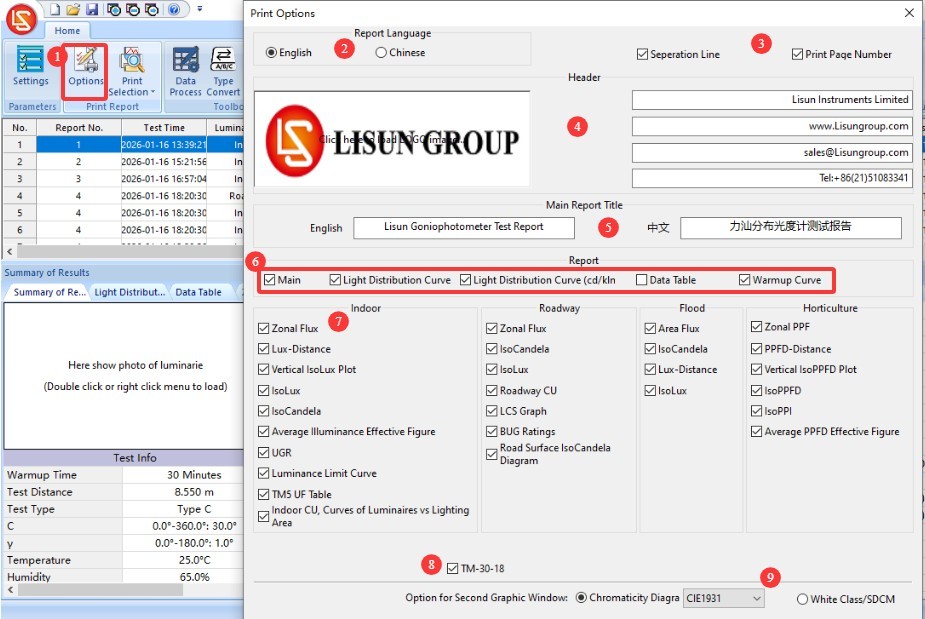
Figura 109
| Număr | notițe |
| ① | Faceți clic pentru a imprima raportul de testare selectat în prezent |
| ② | Faceți clic pentru a imprima toate rapoartele de testare din fișierul bazei de date curente. |
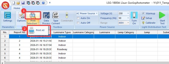
Figura 110
11. Întreținerea și îngrijirea zilnică a echipamentelor
11.1 Întreținerea de rutină
Procedura de pornire: Mai întâi, porniți întrerupătorul principal de alimentare al dulapului; apoi, porniți întrerupătoarele de alimentare pentru echipamentul din interiorul dulapului și din camera obscură unul câte unul; în final, lansați software-ul. Procedura de oprire: Mai întâi, închideți software-ul; apoi, opriți întrerupătoarele de alimentare pentru echipamentul din interiorul dulapului și din camera obscură unul câte unul; în final, opriți întrerupătorul principal de alimentare al dulapului.
Keep the darkroom control room clean and dust-free to prevent dust from entering the equipment. If there is surface dust on the equipment, wipe it off with a dry, soft cloth.
Evitați expunerea camerei obscure la umiditate ridicată pentru perioade lungi de timp; păstrați la îndemână un dezumidificator dacă este necesar.
11.2 Întreținerea de rutină
11.2.1 Cleaning the Photometric Probe
If the darkroom cannot be kept dust-free, clean the light-sensitive surface of the photometer probe regularly (for example, once a month) based on actual conditions to prevent dust from accumulating and affecting test accuracy.
When cleaning, please use a professional lint-free cloth to remove dust without scratching the device.
11.2.2 Lampă standard
Lampa standard este valabilă un an. Dacă totuși trebuie să calibrați camera obscură după un an, vă recomandăm să achiziționați o nouă lămpă standard.
Software 11.2.3
We will update the software from time to time to add features and fix bugs. If you encounter any issues while using the software, please feel free to contact us at any time to obtain the latest version.
11.3 Dezafectare și întreținere pe termen lung
11.3.1 Curățarea și protecția echipamentelor
Thoroughly clean all equipment surfaces, and cover the main unit, probes, and cabinet with dust-proof cloths; disconnect all power sources.
11.3.2 Protecția mediului
Ensure that the darkroom is dry and well-ventilated to prevent equipment from getting damp. If the ambient humidity is high, keep a dehumidifier on hand.
11.3.3 Pornire lunară
Efectuați un test de pornire o dată pe lună pentru a vă asigura că toate componentele hardware ale sistemului funcționează corect.
12. Depanarea și rezolvarea problemelor comune
12.1 Erori de comunicare
Cause of the problem: Check whether the communication cable is securely connected and whether it is plugged into the wrong port; verify that the driver is installed correctly; try a different USB port or communication cable to rule out hardware issues.
Soluție: Reinstalați driverul, conectați cablul de comunicare conform identificatorului dispozitivului, reporniți software-ul și încercați din nou.
12.2 Erori de testare
12.2.1 Anomalii ale fluxului luminos
Cauza defecțiunii: Verificați dacă sursa de lumină este stabilă și dacă timpul de încălzire este suficient; verificați dacă calibrarea echipamentului este validă, dacă distanța de testare este corectă și dacă lumina standard funcționează corect; verificați dacă există interferențe luminoase externe în camera obscură și dacă traiectoria luminii este obstrucționată.
Soluție: Prelungiți timpul de încălzire, recalibrați instrumentul, opriți alte surse de lumină din camera obscură și îndepărtați orice obstrucții de pe calea optică.
12.2.2 Anomalii UGR
Cauza erorii: Dimensiunile suprafeței de emisie a luminii a corpului de iluminat nu au fost introduse; unghiul fasciculului corpului de iluminat este mai mic de 45°; standardul de calcul a fost selectat incorect.
Soluție: Introduceți corect dimensiunile suprafeței de emisie a luminii a corpului de iluminat (lungime/lățime/înălțime); verificați dacă corpul de iluminat este un corp de iluminat de interior (unghiul fasciculului trebuie să fie suficient); selectați standardul CIE 190:2010 și recalculați.
12.3 The Goniophotomoeter does not rotate
Cauza defecțiunii: Verificați dacă alimentarea de la rețeaua principală este pornită și dacă cablajul este corect; verificați dacă regulatorul de unghi din interiorul dulapului funcționează normal; confirmați dacă există obiecte străine blocate în arborele rotativ.
Solution: Check the power supply and wiring, and remove any foreign objects; restart the system and software, then try again.
12.4 Software Malfunctions
12.4.1 Prăbușiri de software
Cauza problemei: Verificați dacă sunteți conectat la sistemul de operare al computerului cu un cont de administrator; verificați dacă software-ul este instalat complet; verificați dacă fișierele bazei de date sunt corupte.
Soluție: Conectați-vă la computer utilizând un cont de administrator; reinstalați software-ul și driverele; creați un nou fișier bază de date.
12.4.2 Software-ul afișează mesajul „Fișierul nu este o bază de date”
Cauza problemei: Fișierul bazei de date a fost șters sau mutat; programul implicit folosit pentru deschiderea fișierelor LGF a fost modificat.
Solution: Create a new database file and save it; restore the default association for LGF files.
12.5 Pană de curent
12.5.1 Anomalii ale ieșirii de curent continuu
Causes of Failure: The cabinet’s AC/DC switch was not set to DC; the sample voltage or current exceeded the DC power supply limits; a short circuit in the sample;
Depanare: Verificați dacă tensiunea și curentul mostrei se încadrează în intervalul de ieșire al sursei de alimentare de curent continuu. De exemplu, DC3005 Modelul are o tensiune maximă de ieșire de 30 V și un curent maxim de ieșire de 5 A. Verificați dacă eșantionul este scurtcircuitat; dacă da, reparați eșantionul înainte de a-l testa din nou.
12.5.2 Fără ieșire CA
Cause of the fault: The cabinet’s AC/DC switch was not set to the AC position; the overload protection was triggered;
Troubleshooting Steps: Check the AC power output wiring and sample connections to ensure there are no loose connections or short circuits; if the overload protection is triggered, turn off the power, allow the unit to cool for 5 minutes, and then restart it. Ensure that the sample power remains within the AC power output range; for example, the LSP-500VARC are o putere maximă de ieșire de 500W.