
 Engleză
 中文简体
中文简体 Русский
 Español
 Português
 Türkçe
 العربية
 Deutsch
 Polski
 Italiano
 Français
 한국어
한국어 ไทย
ไทย Tiếng Việt
 日本語
日本語





























Sarcină electronică continuă programabilă
Manual de utilizare
Aplicabil LISUN modele: M9822,M9822A.M9822B、M9823、M9823A、M9824A、M9835A、M9843A
This manual applies to the M9835A Series Programmable DC Electronic Load.
Informațiile conținute în acest manual pot fi modificate fără notificare prealabilă.
The latest electronic version of the user manual can be downloaded from our official website:
September 2020…………………………………….. First Edition
Declarația companiei
This manual may not cover all aspects of the instrument. Our company reserves the right to make improvements and enhancements to the product’s performance, functions, internal structure, appearance, accessories, and packaging without prior notice. If you have any questions regarding discrepancies between this manual and the instrument, please contact our company.
Siguranță Atenție:
| Risc de electrocutare | Take precautions against electric shock during operation, testing, and instrument maintenance. Non-professionals must not open the instrument case without authorization. If a professional needs to replace a fuse or perform other maintenance, be sure to unplug the power cord first and perform the work only when accompanied by another person. Even after the power plug has been unplugged, the charge stored in the capacitors may still present a dangerous voltage; wait a few minutes for the charge to dissipate before proceeding. Do not replace or adjust the instrument’s internal circuits or components without authorization! | |
Sursa de alimentare de intrare |
Please use a power supply that meets the power specifications for this instrument; using a power supply that does not meet these specifications may damage the instrument. When replacing a fuse, use one of the same specification. | |
| Stay Away from Explosive Gas Environments | Electronic instruments must not be used in environments containing flammable or explosive gases, or in environments containing corrosive gases or dust, to prevent hazards. | |
Alte măsuri de siguranță |
Do not arbitrarily apply external voltage or current sources to the test terminals or other input/output terminals of this instrument. Do not apply AC voltage to the input terminals. | |
You must strictly observe all safety precautions during any operation or maintenance of this instrument. Failure to observe these safety precautions and the warnings in this manual may not only affect the instrument’s performance but may also result in direct damage to the instrument and pose a risk to personal safety. The Company assumes no liability for any consequences resulting from failure to comply with these safety precautions.
1. Noțiuni de bază
Thank you for purchasing and using our company’s products. Before using this instrument, please first inspect and verify the contents against the packing list included in the shipment. If there are any discrepancies, please contact our company as soon as possible to protect your rights.
1.1 Shipping Inspection
Upon receiving this product, please carefully unpack and inspect it following the steps below:
——————————————————————————————————————————-
Warning: If any part of the electronic load (such as the enclosure, front/rear panels, LCD screen, power switch, or port connectors) is damaged during shipping, do not connect the power supply or turn on the power switch, as this may result in an electric shock hazard.
——————————————————————————————————————————-
1. Check the shipping box or shock-absorbing material used to package the electronic load for any damage.
2. Inspect the items included with the electronic load inside the shipping carton for any damage or defects.
3. Check whether all items included in the electronic load’s packaging are the specified accessories or options.
| standard de configurare | Cantitate | notițe |
| M983X Host Computer | unitate de 1 | Model Numbers by Purchase Order |
| Cablu de alimentare | buc 1 | This varies by country (or region). |
| Manual de utilizare | 1 de servire | |
| Test Report/Certificate of Conformity | 1 de servire |
If you encounter any issues during the above inspection, please contact our company or the relevant dealer.
1.2 Verificați sursa de alimentare
Check whether the power supply for the electronic load meets the following requirements:
| Cerinţe | |
| Voltaj | 220/110 (1±10%) V AC |
| Frecvență | 47–63 Hz |
| Consumul maxim de putere | 30 VA |
1.3 Installing Fuses
Fuse Specifications: 250V/1A slow-blow fuse, 520mm mini fuse
The instrument comes with a fuse already installed. Spare fuses are included with the accessories; please replace them with fuses of the specified rating!
To inspect or replace a fuse, first unplug the power cord, then remove the fuse holder.
1.4 Conectați cablul de alimentare
Check the three-wire power cord; one of the wires is the ground wire. When connected to a grounded outlet, it grounds the electronic load unit, thereby protecting the user from the risk of electric shock.
Please make sure the power cord is in good condition before connecting the electronic load to a properly grounded power outlet.
Warning: Never use a power cord that shows any signs of damage to avoid the risk of electric shock.
Warning: Use the provided three-wire power cord with a ground wire to ensure the instrument is properly grounded.
1.5 Cerințe de mediu
Do not use in environments with excessive dust, vibrations, direct sunlight, or corrosive gases.
The instrument should be operated at temperatures between 0°C and 40°C and relative humidity of ≤75%. Please use the instrument under these conditions whenever possible to ensure measurement accuracy.
This instrument has been carefully designed to minimize power supply noise; however, it should still be used in a low-noise environment whenever possible. If this is unavoidable, please install a power filter.
If the instrument will not be used for an extended period, please place it in its original packaging or a similar box and store it in a well-ventilated room at a temperature between 5°C and 40°C and a relative humidity not exceeding 85% RH. The air should be free of harmful impurities that could corrode the instrument, and direct sunlight should be avoided.
Instruments—especially the test leads connected to the device under test—should be kept away from strong electromagnetic fields to prevent interference with the measurement.
Maintain adequate ventilation around the instrument to ensure proper cooling and prevent the internal temperature from rising too high.
Minimum clearance requirements: Back >= 180 mm, both sides >= 60 mm
Electrostatic Discharge (ESD) Protection: Although the instrument has been carefully designed to enhance its resistance to electrostatic shocks, a suitable work area should still be provided to prevent electrostatic discharge.
Provide sufficient space around the instrument so that the power cord can be quickly disconnected in an emergency.
1.6 Pornirea instrumentului
Press the power button in the lower-left corner of the instrument to move it into the recessed position. This turns on the power, and the instrument performs a self-test, loads configuration information, loads initialization data, and initializes the test conditions. Once everything is confirmed to be normal, the startup process is complete.
If the instrument will not be used for an extended period of time, unplug the power cord from the outlet or turn off the main circuit breaker.
2. Prezentare generală
Main Topics in This Chapter: Basic product specifications and feature descriptions, an overview of the front and rear panels and the LCD display, and basic operating procedures.
2.1 Introducere produs
The M983X Series Programmable DC DC Electronic Load. Unit features a high-performance ARM processor paired with a high-performance, high-speed sampling ADC; its 5-inch TFT color screen supports both Chinese and English interfaces, and—combined with a carefully designed, guided menu system—ensures intuitive operation; the display provides rich and comprehensive information, simultaneously showing load operation and fast-charge voltage selection; With a higher display resolution of 0.0001, it enables more precise monitoring of voltage and current details in the products under test; the USB HOST port allows for convenient data storage and firmware upgrades via a USB flash drive; comprehensive comparator functions, combined with the HANDLER interface, ensure more reliable batch testing and systematic testing on production lines; It offers a rich and comprehensive set of load functions: Constant Current (CC), Constant Voltage (CV), Constant Power (CP), Constant Resistance (CR), battery discharge testing (the screen displays real-time discharge curves), dynamic testing (to evaluate the power supply’s dynamic output performance), and list testing (to assess the power supply’s performance under various load conditions); A flexible hardware and software architecture meets user requirements for customized test combinations, thereby improving production line testing efficiency; Intelligent fan control and excellent heat dissipation, combined with comprehensive protection and alarm measures—including overvoltage, overcurrent, overpower, overheat, and reverse polarity protection—ensure greater instrument reliability and safety; The entire instrument series comes standard with an RS232 interface; combined with a comprehensive SCPI command set, it allows for easy connection to a computer for real-time data acquisition and instrument control.
High-performance electronic loads are widely used in production line testing, product qualification, and laboratory R& D across industries such as Voltage Transformers, chargers, switching power supplies, and various types of batteries.
Caracteristici cheie
5-inch TFT high-definition color display with a choice of Chinese or English user interface
Available in multiple power ratings: 1800W, 2400W, 3000W, and 4500W
Display resolution of up to 0.0001 for voltage and current, suitable for a wider range of testing scenarios
500 kHz High-Speed Sampling ADC, Real-Time Measurement of Peak-to-Peak and Peak Values for Voltage and Current (Vpp/Vp+/Vp-/Ipp/Ip+/Ip-)
CR-LED Test Mode: A user-friendly parameter setup mode for greater convenience
OCP test function: automatically detects OCP trip points, automatically determines the maximum power point (Pmax), and automatically measures current and voltage parameters
Dynamic load frequency up to 50 kHz, configurable current slope, real-time measurement of voltage peaks Vp+ and Vp-
Time measurement function, supporting OVP protection point and protection time testing, as well as power-on time and hold time testing, among others
Battery test mode, which can test battery endurance and capacity, and includes internal resistance testing and curve plotting functions
List test mode, which can test the comprehensive parameters of the power supply under various load conditions, including comparator functionality
USB flash drive software update feature—keep your operating system up to date at all times
One-click screenshot feature lets you easily save or share what’s on your screen; the built-in USB HOST port makes it convenient to save data.
The instrument can store 100 sets of configuration files internally and 500 sets externally (on a USB drive), allowing settings to be saved and recalled.
Comes standard with a Handler and an RS-232C interface for convenient online operation and signal output
Compatible with serial communication commands from other major manufacturers; can be used as a direct replacement
Specificații tehnice 2.2
| Model | Model | M9831A | M9837A | M9830A | M9841A | M9834A | M9835A | M9836A | M9843A |
| Valoarea evaluată | Tensiune de intrare | 0-150 V | 0-150 V | 0-150 V | 0-150 V | 0-500 V | 0-500 V | 0-500 V | 0-500 V |
| Valoarea evaluată | Curent de intrare | 0.1 mA la 240 A | 0.1 mA–240 A | 0.1 mA–240 A | 0.1 mA–240 A | 0.1 mA–240 A | 0.1 mA–240 A | 0.1 mA–240 A | 0.1 mA–240 A |
| Valoarea evaluată | Putere de intrare | 1800 W | 2400 W | 3000 W | 4500 W | 1800 W | 2400 W | 3000 W | 4500 W |
| Raza de masurare | Acuratețe | Acuratețe | Acuratețe | Acuratețe | Rezoluţie | Rezoluţie | Rezoluţie | Rezoluţie | |
| Precizie de încărcare | 0-9.9999 V | ±(0.05% + 0.03% FS) | ±(0.05% + 0.03% FS) | ±(0.05% + 0.03% FS) | ±(0.05% + 0.03% FS) | 0.1 mV | 0.1 mV | 0.1 mV | 0.1 mV |
| Precizie de încărcare | 10 V – 99.999 V | ±(0.05% + 0.03% FS) | ±(0.05% + 0.03% FS) | ±(0.05% + 0.03% FS) | ±(0.05% + 0.03% FS) | 1 mV | 1 mV | 1 mV | 1 mV |
| Precizie de încărcare | 100 V–150 V / 500 V | ±(0.05% + 0.03% FS) | ±(0.05% + 0.03% FS) | ±(0.05% + 0.03% FS) | ±(0.05% + 0.03% FS) | 10 mV | 10 mV | 10 mV | 10 mV |
| Precizie de încărcare | 0-9.9999 A | ±(0.05% + 0.05% FS) | ±(0.05% + 0.05% FS) | ±(0.05% + 0.05% FS) | ±(0.05% + 0.05% FS) | 0.1 mA | 0.1 mA | 0.1 mA | 0.1 mA |
| Precizie de încărcare | 10-99.999 A | ±(0.05% + 0.05% FS) | ±(0.05% + 0.05% FS) | ±(0.05% + 0.05% FS) | ±(0.05% + 0.05% FS) | 1 mA | 1 mA | 1 mA | 1 mA |
| Precizie de încărcare | 100-240 A | ±(0.05% + 0.05% FS) | ±(0.05% + 0.05% FS) | ±(0.05% + 0.05% FS) | ±(0.05% + 0.05% FS) | 10 mA | 10 mA | 10 mA | 10 mA |
| Constant Voltage Mode | 1.5 V – 15 V | ±(0.05% + 0.03% FS) | ±(0.05% + 0.03% FS) | ±(0.05% + 0.03% FS) | ±(0.05% + 0.03% FS) | 0.1 mV/1 mV | 0.1 mV/1 mV | 0.1 mV/1 mV | 0.1 mV/1 mV |
| Constant Voltage Mode | 1.5V–150V/500V | ±(0.05% + 0.03% FS) | ±(0.05% + 0.03% FS) | ±(0.05% + 0.03% FS) | ±(0.05% + 0.03% FS) | 10 mV | 10 mV | 10 mV | 10 mV |
| Mod curent constant | 0–6 A / 12 A / 24 A | ±(0.05% + 0.05% FS) | ±(0.05% + 0.05% FS) | ±(0.05% + 0.05% FS) | ±(0.05% + 0.05% FS) | 0.5 mA | 0.5 mA | 0.5 mA | 0.5 mA |
| Mod curent constant | 0–60 A/120 A/240 A | ±(0.05% + 0.05% FS) | ±(0.05% + 0.05% FS) | ±(0.05% + 0.05% FS) | ±(0.05% + 0.05% FS) | 10 mA | 10 mA | 10 mA | 10 mA |
| Fixed Resistance Mode | 0.05 Ω – 5 Ω | ±(0.2% + 0.2% FS) | ±(0.2% + 0.2% FS) | ±(0.2% + 0.2% FS) | ±(0.2% + 0.2% FS) | 0.0001 Ω | 0.0001 Ω | 0.0001 Ω | 0.0001 Ω |
| Fixed Resistance Mode | 0.5 Ω – 50 Ω | ±(0.1% + 0.1% FS) | ±(0.1% + 0.1% FS) | ±(0.1% + 0.1% FS) | ±(0.1% + 0.1% FS) | 0.001 Ω | 0.001 Ω | 0.001 Ω | 0.001 Ω |
| Fixed Resistance Mode | 5 Ω – 500 Ω | ±(0.1% + 0.1% FS) | ±(0.1% + 0.1% FS) | ±(0.1% + 0.1% FS) | ±(0.1% + 0.1% FS) | 0.01 Ω | 0.01 Ω | 0.01 Ω | 0.01 Ω |
| Fixed Resistance Mode | 500 Ω–5 kΩ | ±(1% + 1% FS) | ±(1% + 1% FS) | ±(1% + 1% FS) | ±(1% + 1% FS) | 0.1 Ω | 0.1 Ω | 0.1 Ω | 0.1 Ω |
| Modul de putere constantă | 0–100 V | ±(0.1% + 0.1% FS) | ±(0.1% + 0.1% FS) | ±(0.1% + 0.1% FS) | ±(0.1% + 0.1% FS) | 1 mW | 1 mW | 1 mW | 1 mW |
| Modul de putere constantă | 100–1000 V | ±(0.1% + 0.1% FS) | ±(0.1% + 0.1% FS) | ±(0.1% + 0.1% FS) | ±(0.1% + 0.1% FS) | 10 mW | 10 mW | 10 mW | 10 mW |
| Modul de putere constantă | 1000–4500 V | ±(0.1% + 0.1% FS) | ±(0.1% + 0.1% FS) | ±(0.1% + 0.1% FS) | ±(0.1% + 0.1% FS) | 0.1 W | 0.1 W | 0.1 W | 0.1 W |
| Battery Testing Features | Input Voltage Range: 2–150 V/500 V Maximum Capacity: 9999 Ah Maximum Discharge Time = 1 to 4294,967,295 seconds (> 7 days) | Input Voltage Range: 2–150 V / 500 V Maximum Capacity: 9999 Ah Maximum Discharge Time = 1 to 4294,967,295 seconds (> 7 days) | Input Voltage Range: 2–150 V/500 V Maximum Capacity: 9999 Ah Maximum Discharge Time = 1 to 4294,967,295 seconds (> 7 days) | Input Voltage Range: 2–150 V/500 V; Maximum Capacity: 9999 Ah; Maximum Discharge Time = 1 to 4294,967,295 seconds (> 7 days) | Input Voltage Range: 2–150 V/500 V Maximum Capacity: 9999 Ah Maximum Discharge Time = 1 to 4294,967,295 seconds (> 7 days) | Input Voltage Range: 2–150 V / 500 V Maximum Capacity: 9999 Ah Maximum Discharge Time = 1 to 4294,967,295 seconds (> 7 days) | Input Voltage Range: 2–150 V/500 V Maximum Capacity: 9999 Ah Maximum Discharge Time = 1 to 4294,967,295 seconds (> 7 days) | Input voltage range: 2–150 V/500 V Maximum capacity: 9999 Ah Maximum discharge time = 1 to 4294,967,295 seconds (> 7 days) | Input Voltage Range: 2–150 V / 500 V Maximum Capacity: 9999 Ah Maximum Discharge Time = 1 to 4294,967,295 seconds (> 7 days) |
| Mod de testare dinamică | Minimum pulse width: 0.010 ms; Maximum pulse width: 999 s; Edge resolution: 0.010 ms; Maximum edge duration: 6 s | Minimum pulse width: 0.010 ms; Maximum pulse width: 999 s; Edge resolution: 0.010 ms; Maximum edge duration: 6 s | Minimum pulse width: 0.010 ms; Maximum pulse width: 999 s; Edge resolution: 0.010 ms; Maximum edge duration: 6 s | Minimum pulse width: 0.010 ms; Maximum pulse width: 999 s; Edge resolution: 0.010 ms; Maximum edge duration: 6 s | Minimum pulse width: 0.010 ms; Maximum pulse width: 999 s; Edge resolution: 0.010 ms; Maximum edge duration: 6 s | Minimum pulse width: 0.010 ms; Maximum pulse width: 999 s; Edge resolution: 0.010 ms; Maximum edge duration: 6 s | Minimum pulse width: 0.010 ms; Maximum pulse width: 999 s; Edge resolution: 0.010 ms; Maximum edge duration: 6 s | Minimum pulse width: 0.010 ms; Maximum pulse width: 999 s; Edge resolution: 0.010 ms; Maximum edge duration: 6 s | Minimum pulse width: 0.010 ms; Maximum pulse width: 999 s; Edge resolution: 0.010 ms; Maximum edge duration: 6 s |
| Mod de testare Listă | Constant voltage, constant current, constant power, constant resistance, short circuit, open circuit | Constant voltage, constant current, constant power, constant resistance, short circuit, open circuit | Constant voltage, constant current, constant power, constant resistance, short circuit, open circuit | Constant Voltage, Constant Current, Constant Power, Constant Resistance, Short Circuit, Open Circuit | Constant voltage, constant current, constant power, constant resistance, short circuit, open circuit | Constant voltage, constant current, constant power, constant resistance, short circuit, open circuit | Constant voltage, constant current, constant power, constant resistance, short circuit, open circuit | Constant voltage, constant current, constant power, constant resistance, short circuit, open circuit | Constant voltage, constant current, constant power, constant resistance, short circuit, open circuit |
| Dimensiuni | 435 200 mm x mm x mm 510 | 435 200 mm x mm x mm 510 | 435 200 mm x mm x mm 510 | 435 200 mm x mm x mm 510 | 435 200 mm x mm x mm 510 | 435 200 mm x mm x mm 510 | 435 200 mm x mm x mm 510 | 435 200 mm x mm x mm 510 | 435 200 mm x mm x mm 510 |
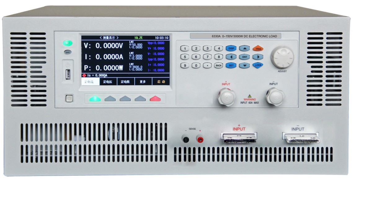
2.3 Introduction to the Front Panel
6
5
4
3
2
1
879
7
9 8 10
| Nu. | Nume | notițe |
| 1 | Întrerupător | To turn the instrument on or off, the retracted position indicates “on,” and the extended position indicates “off.” |
| 2 | Port gazdă USB | Used to connect a USB flash drive. Supports the FAT16 and FAT32 file systems. Supports firmware updates, recording test data, saving screen images, and saving and loading test parameter files, among other features. |
| 3 | Taste funcționale | SAVE button: Used to start saving data to the USB drive; the button light flashes while data is being recorded. |
| 4 | Display LCD | Displays measurement results, fast-charge voltage control, test conditions, system information, and more. |
| 5 | Tasta de intrare | A full-featured numeric keypad used for entering data or typing characters when prompted to enter information such as file names or notes. |
| 6 | mâner | Used to adjust settings and navigate menus by moving left and right |
| 7 | Low-current input terminals: Red is positive, black is negative | Reverse polarity voltage input may cause high currents, which is extremely dangerous. |
| 8 | Terminal la distanță | For the remote voltage input, enable remote measurement mode in the menu to reduce wire voltage drop during high-current input. |
| 9 | Function Soft Keys | The functions of the five buttons in this section vary depending on the function page; that is, their functions are not fixed and differ across menus. The corresponding functions are displayed above the respective buttons. |
| 10 | High-Current Input Terminals | Reverse polarity voltage input may cause high currents, which is extremely dangerous. |
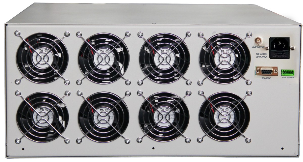
2.4 Introduction to the Rear Panel
321
4
65
| Nu. | Nume | notițe |
| 1, 2 | Grila de ventilație | Do not block the opening; keep the area well-ventilated. |
| 3 | I-MONITOR Interface | |
| 4 | Intrare alimentare CA. | Includes a fuse, rated at 1A (customizable for special voltages) |
| 5 | RS232C Interfață serială | It provides a serial communication interface between the instrument and external devices; parameter settings, commands, and other functions can be configured and retrieved via a computer, enabling remote control without the need for an instrument panel. |
| 6 | Bloc terminal | Please connect the wires according to the printed markings. |
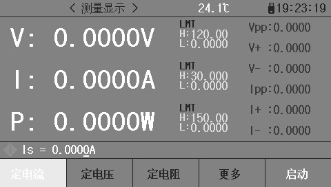
2.5 Introduction to the Display Area
The LCD display is divided into several relatively fixed areas that show specific information for each page.
65432
1
7
| Nu. | Nume | notițe |
| 1 | Settings and Status Bar | Help Tips for Load Parameter Settings and Menu Settings |
| 2 | Real-time data shows | Displays real-time voltage, current, and power parameters |
| 3 | Internal Temperature of the Machine | Real-time Temperature Monitoring Display Inside the Machine |
| 4 | Limit Comparisons and Ripple Display | You can open the comparison items in the menu for stress testing. |
| 5 | System Icon Display | Display system status as icons: USB drive connected; remote control status; |
| 6 | Clock Display Area | Displays the real-time clock. You can change the date and time on the System Configuration page, or turn off the clock display. |
| 7 | Zona funcțională | Unit Conversion and Instrument Operating Mode Settings |
3. Menu Operations
Main Content of This Chapter: A detailed description of the information displayed on all menu screens of the electronic load and how to operate them.
3.1 Loading a Page
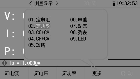
| Numele domeniului | Scurtă descriere |
| Constant Current (CC) (Fixed) | Regardless of whether the input voltage changes, the electronic load draws a constant current. |
| Constant Voltage (CV) (Fixed) | The electronic load draws enough current to keep the input voltage constant at the set value. |
| Flexibly Define Keys | This field is a flexible menu whose options are determined by the “More” menu. |
| Mai Mult | Pressing this key brings up the function selection screen, which includes the following menu options: Fixed Resistance, Fixed CR, Power CP, CC+CV, CR+CV, Short Circuit (SHORT), Battery Test, Dynamic Test, List Test, and LED Mode. You can select an option by using the cursor or by directly entering the corresponding number; once selected, the option will appear in the user-definable key position. |
| acasă | Used to turn the load input on and off |
3.1.1 Routine Page Testing Procedures
3.1.2 Constant-Current Operating Mode (CC)
In constant-current mode, the electronic load draws a constant current regardless of changes in the input voltage.
I
(Set Current)
Curent de încărcare
V
Tensiune de intrare
Press the [Constant Current] button to enter constant current mode; the button indicator will light up. Use the numeric keys to enter the desired current value; the entered number will appear in the status bar. Once you have finished entering the value, press the [Ent] button to confirm. Press the [Start] or [ON] button to begin the load measurement.

Example: Set the constant current to 1.2345 A.
In constant-current mode, enter 1.2345 using the numeric keypad, then press the [Ent] key to confirm.
While the load is running, you can use the [▲] or [▼] keys to move the cursor, turn the knob to change the settings, or use the number keys to reset the parameters; the load will automatically adjust to the new values.
3.1.3 Constant-Voltage (CV) Operating Mode
In constant-voltage mode, the electronic load will draw enough current to maintain the input voltage at the set value.
V
(Set Voltage)
Tensiune de intrare
I
Curent de încărcare
Note: To set or change the voltage value, refer to the instructions for setting a constant current.
Note: When the source voltage is lower than the set value, the load will not be able to operate at a constant voltage.
Note: The difference between the source voltage and the set voltage will be dissipated across the source’s internal resistance and the lead resistance. If this difference is large and the internal resistance is low, the load may draw a significant amount of current!
3.1.4 Constant-Power (CP) Operating Mode
In constant-power mode, the load consumes a constant amount of power. When the input voltage changes, the load adjusts the current to maintain a constant power consumption.
V
V1
Tensiune de intrare
V2 (Rated Power P)
V3
I1 I2 I3 I
Curent de încărcare
In other load modes, press the [More] button to enter the menu and select the constant-power mode, then use the [Start] button to start or stop operation.
When the load is not running, you can change the setpoint using the cursor and knob, or press the [Constant Power] button and use the numeric keys to enter a new value.
Note: To change the power setting, refer to the constant-current method.
3.1.5 Fixed Resistance Operating Mode (CR)
In fixed-resistance mode, the load is treated as a constant resistance, and the load draws a current that varies with changes in the input voltage.
I
Slope (Resistance Setting)
Curent de încărcare
V
Tensiune de intrare
Note: To change the resistance setting, refer to the constant-current method.
3.1.6 CC+CV Mode
The CC+CV mode, or constant current plus constant voltage mode, is primarily designed to prevent damage to the power supply under test caused by overcurrent discharge. Setup and testing procedures:
In the “More Measurement Modes” menu, select “CC+CV” with the cursor, then press the [ENT] key to confirm. Press the [Constant Current] key to set the constant current parameters, and press the [Constant Voltage] key to set the operating parameters for constant-voltage load operation.
Press the Start button to begin the measurement. If the load tester determines that a constant current can be applied up to the set value, the load operates in constant-current mode. If the load tester determines that the power supply cannot output the set current, it will switch to constant-voltage mode, at which point the load’s maximum output current is displayed.
3.1.7 CR+CV Model
The CR+CV mode functions identically to the CC+CV mode; refer to the CC+CV mode for setup and testing procedures.
3.2 Pagina Setări
Press the [SET] button to enter the main menu screen. Use the directional buttons or turn the dial to move the cursor, or enter the first two digits of the menu directly to select the menu you want to access.
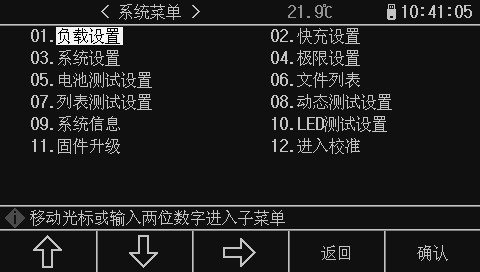
3.2.1 Load Settings Page
From the main menu, use the cursor to select the “Load Settings” option, then press the [ENT] key to enter, or press the number 01 directly to enter.
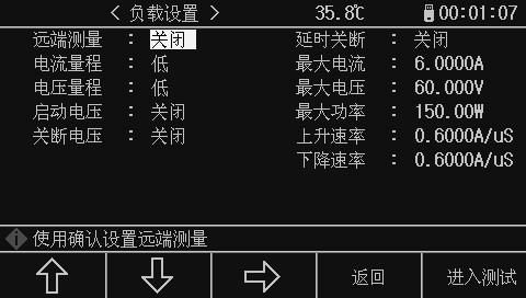
3.2.1.1 Remote Measurement
In CV, CR, and CP modes, the voltage sampling accuracy affects the operational accuracy of the electronic load. When the load draws a large current, a voltage drop occurs across the connection line between the power supply under test and the load. To ensure measurement accuracy, the load provides a remote measurement terminal on its rear panel; users can use this terminal to measure the output voltage of the instrument under test.
Use the [ENT] key to change the menu settings; each time you press the [ENT] key, the menu toggles between open and closed.
Remote Voltage Measurement = On: Enables remote testing; the instrument samples the voltage from the remote measurement terminal on the rear panel.
Remote Voltage Measurement = Off: Disables remote testing; the instrument samples the voltage from the front-panel load input.
Note: For the pin configuration of the rear panel Sense interface, please refer to Appendix A.
3.2.1.2 Delayed Shutdown
Automatic delayed shutdown can be applied to the four basic load modes: constant voltage, constant current, constant power, and constant resistance. If automatic delayed shutdown is enabled, the timer will start counting in seconds once the load is activated, and the load will automatically shut down after the specified delay period has elapsed.
Enter the setting directly using the number keys, press the [ENT] key to confirm; entering 0 turns it off.
Note: The unit is seconds (s), and the setting range is 1 to 99999 s.
Note: If the setting is 0 or close to 0, the “Auto Off” option will be set to “Off,” meaning this feature is disabled.
3.2.1.3 Interval de curent
This model is set to the low current range and cannot be switched.
3.2.1.4 Curent maxim
The maximum load current serves two main purposes:
1. The configurable constant current value (Is=) will be limited to a value below this maximum current;
2. During CV, CP, CR, and short-circuit tests, if the load current exceeds the maximum current, the instrument will trigger an alarm and display an overcurrent (OC) protection warning; if the current remains above the maximum for an extended period, the load may shut down automatically.
Tip: To set the maximum current, simply enter the number and press the [ENT] key to confirm.
3.2.1.5 Interval de tensiune
This model is set to the low-voltage range and cannot be switched.
3.2.1.6 Maximum Voltage
Setting the maximum input voltage serves two main purposes:
1. The configurable voltage value (Vs=) will be limited to a value below this maximum voltage;
When the input voltage exceeds the maximum voltage, the electronic load will trigger an alarm and display “Exceed Voltage!!!,” and the load will shut down;
Tip: To set the maximum voltage, simply enter the number and press the [ENT] key to confirm.
3.2.1.7 Putere maximă
This specifies the maximum power that the load is allowed to consume. If the actual power consumption exceeds this value, the instrument will sound an alarm, display “Power Protection” (OP), and may cause the load to shut down automatically.
Tip: To set the maximum power, simply enter the number and press the [ENT] key to confirm.
3.2.1.8 Starting Voltage
The minimum startup voltage can be applied to the four basic load modes: constant voltage, constant current, constant power, and constant resistance. If the minimum startup voltage is enabled, after the load is started, when the input voltage is lower than the minimum startup voltage, the load will enter a standby state, and the status information area will display “…”. Once the input voltage exceeds the minimum startup voltage, the load will automatically start up.
Example: To set the minimum startup voltage to 1.25 V, navigate to the “Minimum Startup Voltage” menu option, enter [1][.][2][5], and press the [Ent] key to confirm. The default unit is V.
Note: If the set value is 0 or close to 0, the minimum start voltage will be displayed as “Off,” meaning this function is disabled.
Note: Setting the trigger voltage in list test mode enables the automatic startup feature. When the instrument detects that the input voltage exceeds the set voltage, the list test begins; it stops once the test sequence is complete, enabling fully automatic measurement without the need to press any buttons.
3.2.1.9 Turn-off Voltage
The minimum shutdown voltage can be applied to the four basic load modes: constant voltage, constant current, constant power, and constant resistance. If the automatic shutdown voltage is enabled, the load will automatically shut down once the input voltage falls below the automatic shutdown voltage after the load has been activated.
Note: The setup procedure is the same as for the minimum startup voltage.
Note: If the setting is 0 or close to 0, the auto-shutdown voltage will be displayed as “Off,” meaning this feature is disabled.
3.2.1.10 Climb Rate
Used to set the load ramp rate to reduce overcurrent surges caused by sudden load application in certain situations. After entering the data, press [Ent] to confirm; the maximum current that can be set is 3.000 A/μs.
3.2.1.11 Descent Rate
Used to set the time required to transition from normal operating conditions to no-load conditions. After entering the data, press [Ent] to confirm; the maximum current that can be set is 3.000 A/μs.
Note: Once all menu settings are complete, you can press the [Enter Test] button to go directly to the main test page, or press the [Back] button to return to the main menu.
3.2.2 Limit Settings Page
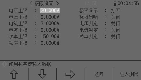
On this page, you can set the voltage, current, and power threshold parameters, and the results will be displayed in the display area of the main test interface; values exceeding the set thresholds will be highlighted in red.
Tip: Move the cursor to the position you want to set, type in the number, and press the [Ent] key to confirm. To set the limit check, press the [Ent] key to enable or disable it. Once you’ve finished setting parameters, press the [Enter Test] key to go directly to the main test page, or press the [Back] key to return to the main menu.
3.2.3 System Settings Page
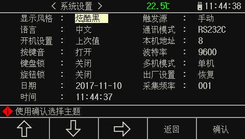
On this screen, you can set and change the instrument’s system style and applications. Press the [Ent] key to cycle through the menu options at the cursor’s location. To set the date and time, simply enter the numbers using the numeric keys and then press [Ent] to confirm.
| Nume meniu | Second-Level Menu Content |
| Stil de afișare | Minimalist Gray |
| Stil de afișare | Fresh Grass Green |
| Stil de afișare | Cool Negru |
| Stil de afișare | Albastru elegant |
| Sursa de declanșare | Manual (MAN): Triggered by the “TRIG” button on the instrument panel |
| Sursa de declanșare | External (EXT): External trigger, triggered by the Sense interface on the rear panel |
| Sursa de declanșare | Bus (BUS): Triggered by programmable commands via the RS232interfata C |
| Limbă | Chineză |
| Limbă | ENGLEZĂ |
| Mod de comunicare | RS232C |
| Mod de comunicare | USB-CDC |
| Mod de comunicare | USB-TMC |
| Setări de pornire | Valoare implicită |
| Setări de pornire | Ultima valoare |
| Adresă locală | After entering a number, press the [Ent] key to confirm. |
| Keypress sounds | Operatii Deschise |
| Keypress sounds | Închide |
| Viteza de transmisie | 4800 9600 19200 38400 57600 |
| Blocarea tastaturii | Open: Lock the 0–9 numeric keypad when opening |
| Blocarea tastaturii | Închide |
| Multi-Machine Mode | Un singur jucator |
| Multi-Machine Mode | Mai multe mașini |
| Blocare butonului | Operatii Deschise |
| Blocare butonului | Închide |
| Setări din fabrică | Restore: Once you confirm the restore, all settings will be reset to factory defaults. Please proceed with caution. |
| Frecvența de eșantionare | Used to set the data collection time when saving data to a USB drive |
| Data | Press the number key directly, then press the [Ent] key to confirm, and move the cursor to the next item. |
| Timp | Press the number key directly, then press the [Ent] key to confirm, and move the cursor to the next item. |
3.2.4 File List Page
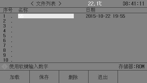
3.2.4.1 Storage and Retrieval
Using the save and recall functions, you can instantly save parameters, store measurement settings in internal ROM or on an external USB storage device, and save measurement results or screenshots to an external USB storage device.
Caracteristici de stocare
The instrument’s storage system provides the following saving functions:
Instantly save user-edited data and settings;
Instantly save measurement settings and system configuration parameters;
Save the measurement settings as a file to the internal ROM or an external USB storage device;
Save screenshot files to a USB drive (screenshot feature);
Save measurement results to a USB flash drive (data logging function).
Funcția de apel
Once stored, the following functions can be called:
Instantly and automatically apply user-corrected data and settings;
Instantly and automatically apply the measurement settings;
Instantly and automatically retrieve system configuration parameters;
Load measurement configuration files from the internal ROM or an external USB storage device using the file management feature;
Storage Media Types
The instrument uses the following media to store information:
| Media Type | Utilizeaza |
| Internal RAM (battery-powered) | Instantly save measurement parameters and system settings |
| Internal FLASH ROM | User-edited data and settings, measurement configuration files |
| External USB Storage Device (USB Flash Drive) | Measurement configuration files, screenshot files, data log files |
Tip: On the file list page, type the number directly. Numbers 0–100 correspond to RAM storage, while numbers above 100 correspond to USB drive storage. The storage type will be displayed on the right side of the operation bar. After entering the file code, press the Save button to confirm.
USB Flash Drive File Structure
When a USB flash drive is connected to the instrument, the instrument organizes and uses the folders and files on the drive according to a predetermined structure.
As shown in the table below:
| Tip fișier | Extensia de fișier | Maximum number of files*1 | File path*2 |
| Measurement Configuration File | EST | 500 | 6311SETUP |
| Data Log File | CSV | 200 | 6311DATE |
| Screenshot Files | GIF, BMP, PNG | 200 | 6311IMAGE |
| Update Files | 36U | 10 | Director rădăcină |
Note *1. Refers to the maximum number of files with the same file extension; Note *2. Folders vary depending on the instrument model.
——————————————————————————————————————————-
Note: The folder is automatically created by the instrument, and—with the exception of update files—the filenames are also automatically generated by the instrument using a numbering system.
——————————————————————————————————————————-
USB flash drives must be compatible with the FAT16 or FAT32 file system and must be formatted using FAT16 or FAT32.
USB drives with version 3.0 are not currently supported. If the instrument fails to recognize a USB drive, please use a different, formatted USB drive.
——————————————————————————————————————————-
Note: The Company assumes no responsibility for any data loss on USB flash drives resulting from their use with this device.
——————————————————————————————————————————-
3.2.4.2 Saving a File to a USB Drive (USB 2.0)
After connecting a USB flash drive to the instrument’s USB (HOST) port, you can use the [SAVE] button on the front panel to save test results or screen shots to the USB flash drive.
Save the measurement results to a USB flash drive
Press the [SAVE] button on any page, and the following prompts will appear at the bottom of the instrument display: the [Graph] and [Data] prompts. On any measurement page, pressing the [Data] key saves the measurement results to a USB drive in CSV format, while pressing the [Graph] key captures a screenshot of the current display and saves it. During data saving, the [SAVE] key will flash; press [SAVE] again to complete the save. While saving a [Graph], the [SAVE] button remains lit; it turns off once saving is complete. After saving, you can download the files to a PC to open and use them.
A single CSV or TXT file can store up to 65536 rows of test data; once this maximum is reached, the instrument automatically stops recording data.
Warning: Do not remove the USB flash drive while data is being written to it, as this may damage the USB flash drive or its file system.
Note: Data log files are numbered sequentially from 000 to 199; users cannot specify or modify the file names. Writing data to the USB drive may take some time, and measurements may temporarily stop responding during this process.
Data recording will automatically end abnormally in the following situations:
Failed to write data to the USB flash drive
The number of data rows written to a file exceeds the limit
Save the screenshot to a USB flash drive
On any display page, you can save the current screen content as an image in BMP format to a USB flash drive. Once saved, you can download the files to a PC to open and use them.
Follow these steps to save a screenshot:
Step 1: Connect the USB flash drive and verify that the device has successfully recognized it; a USB flash drive icon should appear in the upper-right corner of the screen;
Step 2: Select the page you want to take a screenshot of;
Step 3: After pressing the [SAVE] button, the screen will display [Graphics] and [Data] prompts at the bottom. Press the [Graphics] button to begin saving. The [SAVE] button will remain lit; it will turn off once saving is complete. The screen snapshot will then be saved to the USB drive as a file in the specified image format.
Note: Screenshot files are numbered sequentially from 000 to 199; users cannot specify or modify the file names when saving.
3.2.4.3 List of Documents
Overview of Measurement Configuration Files
Test settings refer to the parameters related to measurements. These parameters include: the current page (or the page displayed before accessing the file list); all settings on the Measurement Settings page; and all settings on the Limits Settings page.
The instrument organizes the above settings into a single file, which can be saved and loaded in its entirety; you can also specify a name (remark) for the saved file, and this name is saved along with the file.
Measurement configuration files can be saved by number on the following media:
| Mass-media | Număr de stocare | Utilizare |
| Internal RAM (battery-powered) | 0 | File is not visible; save immediately; call automatically |
| Internal FLASH ROM | 1-100 | Storing and Retrieving via File Lists |
| Dispozitiv de stocare USB extern | 101-550 | Storing and Retrieving via the File List Storage Location: U2826SETUP6311SETUP*1 File Names: 51. EST–550. EST |
Save/Load Measurement Settings
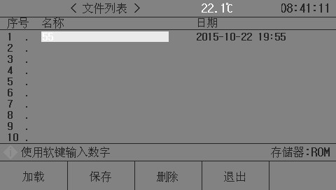
Field information on the file list page:
| Câmp | Descriere |
| Nu. | Displays the numbers of the stored configuration files: 1–100 correspond to the internal ROM memory, and 101–550 correspond to the external USB storage. Use the arrow keys or enter a number directly to select the file number you want to work with: Press the [Save] key to select the storage medium. |
| Nume (NUME) | Displays the notes associated with the saved configuration file, which are used to name the measurement settings; this does not refer to the filename stored on the USB drive. |
| Data (DATA) | Displays the system time at the time of saving. |
| Memorie | Displays the currently active storage medium and automatically switches based on the file number. |
Use the arrow keys to navigate through the fields, select the file number you want to edit, and press the function soft key to proceed:
Function Soft Keys: Operation Functions
Available when a LOAD file exists; calls the specified configuration file
A confirmation step occurs during loading.
Save (SAVE) saves the current measurement settings. You will be prompted to enter a file name before saving; you can simply confirm to use the default name < Unnamed>.
——————————————————————————————————————————-
Note: The file name requested here is actually the comment for the measurement settings file!
——————————————————————————————————————————-
The DELETE command is available when a file exists; it deletes the specified configuration file.
A confirmation prompt appears when deleting.
Exit (EXIT) Exits the file list and returns to the page displayed before entering the file list.
3.2.5 Battery Test Page
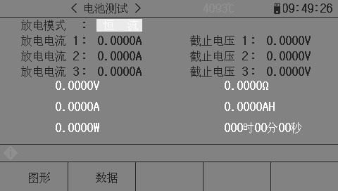
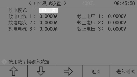
Discharge testing can operate in either constant-current or constant-resistance mode to measure the discharge time and capacity of battery-type power sources. During continuous discharge, the battery voltage drops steadily; when the load input voltage falls below the set value, the discharge test automatically stops, and the instrument displays the discharge time and battery capacity. The instrument allows for the configuration of up to three discharge current levels and cut-off voltages to better simulate the behavior of actual batteries under different current conditions. Discharge current 1 automatically switches to 2 and then to 3 once the conditions are met; therefore, when setting the cut-off voltages, the voltage decay gradient must be followed—cut-off voltage 3 must not exceed 2, and cut-off voltage 2 must not exceed 1.
Battery testing is set up and conducted according to the following procedure:
Step 1: Select the discharge mode; press the [ENT] key to choose constant current or constant resistance;
Step 2: Set the discharge current and cutoff voltage by entering the values directly using the numeric keys, then press the [ENT] key to confirm;
Step 3: Press the button to enter test mode. The load will then enter discharge mode. Press the Start button to begin the test. The screen will display the discharge voltage, current, power, resistance, capacity, and discharge time. Once the discharge is complete, press the icon button to view the battery’s real-time discharge curve.
Note: Discharge parameters can be saved to a USB flash drive in real time. Insert the USB flash drive while the device is in test mode, press the [SAVE] button, and select the data. All discharge data will then be recorded to the USB flash drive, and the discharge curve can be saved as an image.
Note: The graph will not appear until the discharge is complete. At that point, you can press the Graph button to view the entire discharge curve.
3.2.6 Transient Test Page
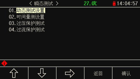
The “Transient” page includes four measurement modes:
Dynamic Measurement Mode
Time Measurement Mode
Overvoltage Protection Test Mode
Overcurrent Protection Test Mode
1. Dynamic Measurement Mode:
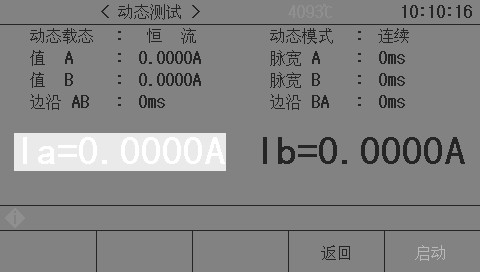
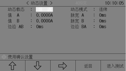
Dynamic testing allows the load to switch back and forth between two voltages or currents; this feature can be used to test the dynamic characteristics of a power supply.
Dynamic testing is set up and conducted according to the following procedure:
Step 1: Select the load type for dynamic testing, then press the [ENT] key to select constant current or constant voltage:
Step 2: Select the dynamic load mode, enter the number directly using the numeric keys, and then press the [ENT] key to confirm;
Continuous (CONT): The load switches automatically after a specified delay;
Trigger (TRIG): Pulse width has no effect; the load switches in response to the trigger signal.
PULS: The load operates at value A. Upon triggering, it switches to value B, and after a delay equal to the width of pulse B, it switches back to value A;
Step 3: Set the value for Point A. After entering the Load A menu, simply enter the number and press the [Ent] key to confirm. The unit depends on whether the load type is A or V.
Step 4: Set the pulse width at Point A. After entering the Pulse Width A menu, simply enter the number and press the [Ent] key to confirm. The unit is 1 ms.
Step 5: Set the value and pulse width for Point B in sequence
Step 6: Set the edges AB and BA, specify the time required for the load value to change from point A to point B, enter the array, and press the [Ent] key to confirm. The unit is ms.
Step 7: Once the setup is complete, press “Enter Test” to go directly to the test page, then press the “Start” button to begin the measurement.
Once the dynamic test begins, the load will continuously switch between values A and B, maintaining width A and width B, respectively.
I
Ib
Ia
TaTbTa Tb t
Start Stop
2. Time Measurement Mode
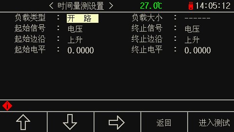
This feature is used to test the time interval between two trigger signals. Under predetermined load conditions, the system automatically measures the time between the two signals with an accuracy of 0.1 ms.
Load types can be selected as open circuit, constant current, constant voltage, constant resistance, or constant power.
You can enter the load size directly using the number keys.
Start and stop signals can be configured as voltage, current, or external triggers.
The rising and falling edges can be set to rising or falling.
The initial level can be entered directly by pressing the number keys.
3. Overvoltage Protection (OVP) Test Mode
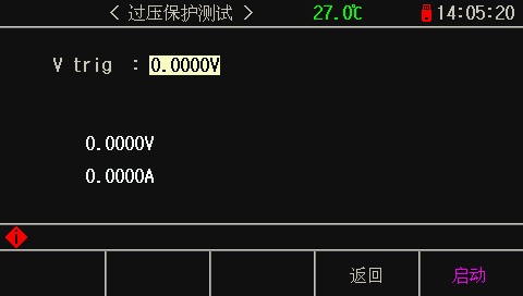
This function is used to measure the input voltage and its falling edge. It triggers when the voltage reaches the set falling-edge voltage, which corresponds to the overvoltage protection threshold of the power supply under test. The time interval from the peak voltage to the trigger point represents the OVP response time of the power supply under test.
4. Overcurrent Protection Test Mode (OCP)
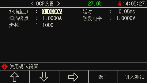
The OCP test function is used to capture critical parameters prior to power protection. The system automatically steps toward the end point at a preset scan current and stops when the trigger threshold is reached, displaying the captured critical value.
3.2.7 List Test Page
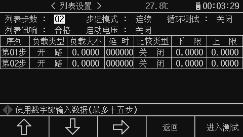
The list testing feature allows for automatic switching between different load modes at preset intervals.
For power supply products and chargers, conducting multi-parameter mixed testing provides a more comprehensive and in-depth understanding of the operational characteristics of the tested products in various application scenarios.
This instrument allows for the configuration of up to 15 test steps with different types or sizes of loads. The automatic test duration for each step ranges from 1 to 60000 seconds, and it can compare current, voltage, or power parameters during each test step to determine whether the test passes or fails. After all configured test steps are completed, the status information area displays an overall pass/fail result: “PASS” if all test steps pass, and “FAIL” if any single step fails.
| Nume meniu | Second-Level Menu Content | Second-Level Menu Content |
| Number of steps in the list | Use the number keys to enter the total number of steps in the list, then press the [Ent] key to confirm. Maximum of 15 steps. | Use the number keys to enter the total number of steps in the list, then press the [Ent] key to confirm. Maximum of 15 steps. |
| Step Mode (Press the [Ent] key to switch) | Continuous: Automatically proceeds to the next step after the specified delay period has elapsed | Continuous: Automatically proceeds to the next step after a preset delay. |
| Step Mode (Press the [Ent] key to switch) | Trigger: After the set delay time has elapsed, wait for the trigger signal before proceeding to the next step. | Trigger: After the set delay time has elapsed, wait for the trigger signal before proceeding to the next step. |
| Loop Test (Press the [Ent] key to toggle) | Start: Run the test in a loop until the Stop button is pressed | Press to start: The test will run in a loop until the Stop button is pressed. |
| Loop Test (Press the [Ent] key to toggle) | Stop: Stops after the test is completed based on the set number of steps | Stop: Stops after the test is completed based on the set number of steps |
| List Alerts (Press the [Ent] key to toggle) | Pass: A buzzer sounds when the test is passed. | Pass: A buzzer sounds when the test is passed. |
| List Alerts (Press the [Ent] key to toggle) | Fail: A buzzer sounds when the test fails. | Fail: A buzzer sounds when the test fails. |
| Start-up Voltage: Enter the voltage using the numeric keys | After setting the trigger voltage, the list test begins when the instrument detects that the input voltage exceeds the set voltage, and stops once the test sequence is complete, enabling automatic measurement without the need to press any buttons. | After setting the trigger voltage, the list test begins when the instrument detects that the input voltage exceeds the set voltage, and stops once the test sequence is complete, enabling automatic measurement without the need to press any buttons. |
| Tipul de încărcare | Faceţi loc | Press the [Ent] key to select |
| Tipul de încărcare | Scurt circuit | Press the [Ent] key to select |
| Tipul de încărcare | Curent constant | Press the [Ent] key to select |
| Tipul de încărcare | Tensiune constantă | Press the [Ent] key to select |
| Tipul de încărcare | Rezistență fixă | Press the [Ent] key to select |
| Tipul de încărcare | Fixed Power | Press the [Ent] key to select |
| Dimensiunea încărcăturii | Enter the number, then press the [Ent] key to confirm. | Enter the number, then press the [Ent] key to confirm. |
| Timp de intarziere | After entering a number, press the [Ent] key to confirm; the unit is 0.1 seconds. | After entering a number, press the [Ent] key to confirm; the unit is 0.1 seconds. |
| Comparison Types | Off: Test data is not compared | Off: Test data is not compared |
| Comparison Types | By Voltage: Test data compared by voltage | By Voltage: Test data compared by voltage |
| Comparison Types | By Current: Test data compared by current | By Current: Test data compared by current |
| Comparison Types | By Power: Comparison of Test Data by Power | By Power: Comparison of Test Data by Power |
| Limita inferioara | Enter the number, then press the [Ent] key to confirm. | Enter the number using the numeric keys and press the [Ent] key to confirm. |
| Limita superioară | Enter the number, then press the [Ent] key to confirm. | Enter the number, then press the [Ent] key to confirm. |
Tip: Move the cursor to fill in all the data, then press the “Enter Test” button to go to the test page.
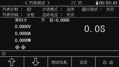
Note: Go to the test page to start the measurement; the page displays the measurement and evaluation results for the current test step.
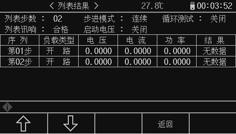
Note: Go to the test results page to view the test data and evaluation results for each step.
3.2.8 LED Test Page
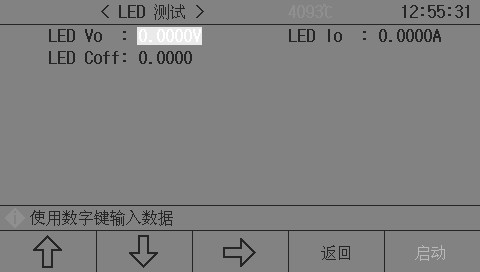
The CR-LED test mode can realistically simulate the characteristics of LED lamps. By adjusting the diode forward voltage setting, it fully simulates the operating principle of a diode, ensuring that the test voltage and current reach normal, stable levels. This avoids the voltage and current instability or oscillations that occur in traditional fixed-resistance modes, thereby accurately reflecting the actual load conditions of the LED driver.
| parametrii | notițe |
| LED Vo | Reference Values for LED Power Supply Output Voltage |
| LED Io | LED Rated Output Current |
| Rd Coefficient | The Rd coefficient is typically set between 0.1 and 0.3. |
Once all parameters have been set, press the Start button to begin the test. The display will show the voltage, current, resistance, and power values of the power supply under test.
3.2.9 System Information Page
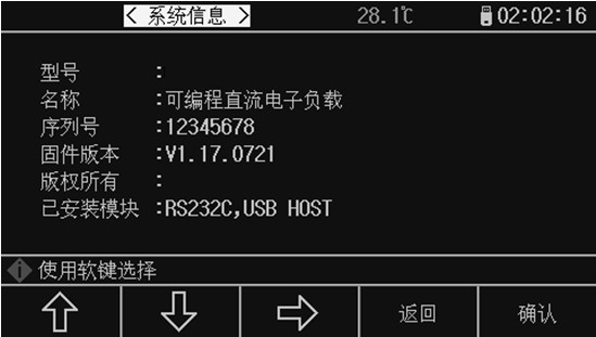
Displays all system information and installed modules for this machine; no changes can be made on this page.
3.2.10 Data Calibration Page
This page is for load data calibration. It is primarily used to verify load data before the product leaves the factory, and a password is required to access it.
3.2.11 Firmware Update Page
The update feature can only be enabled after the USB flash drive connected to the USB (HOST) port has been successfully recognized.
The curing software for the instrument can be easily upgraded. If you encounter any software issues during use, please feel free to contact our company at any time.
Urmați acești pași pentru a actualiza firmware-ul:
Step 1: Download the update file provided by our company; the filename typically includes the instrument model number and has the .97F extension. If it is a compressed file, please unzip it;
Step 2: Copy it to the root directory of a USB flash drive formatted as FAT32 or FAT16;
Step 3: With the instrument to be upgraded powered on, insert the USB flash drive into the USB-HOST port on the front panel;
Step 4: After the USB drive is successfully installed, select the “Firmware Update” menu to enter the firmware update screen, which displays a list of update files on the USB drive (up to 10). The file names are displayed as the instrument model and update date.
——————————————————————————————————————————-
Note: The device displays a maximum of 10 update files. You can use a PC file manager to delete some of the invalid files.
Note: Files that conform to the update file format will be displayed, but the instrument will install them only after they have passed the update verification.
——————————————————————————————————————————-
Step 5: Use the arrow keys to select the update file appropriate for this device, then press the “Update” soft key;
Step 6: After confirming the upgrade, the instrument verifies the upgrade file. If the verification is successful, the upgrade file is installed into the FLASH ROM, and the device automatically reboots once the installation is complete.
You can check the latest firmware version on the “System Information” page.
Note: Do not interrupt the power supply during the upgrade process; doing so may damage the instrument’s firmware, rendering it inoperable and requiring return to the factory for repair.
Appendix A: Interface Specifications
A.1 Remote Measurement
When the load draws a large current, a voltage drop occurs across the connection line between the power source under test and the load, thereby affecting the accuracy of voltage measurements. In CV, CR, and CP modes, the accuracy of voltage sampling affects the operational accuracy of the electronic load.
The purpose of remote measurement is to measure the voltage directly from the power supply under test using two additional test leads, rather than from the load input terminals.
The two voltage sampling wires for remote measurement are located on the Sense connector on the rear panel.
To use remote measurement, you must enable the remote measurement switch in the load settings.
A.2 External Trigger
During dynamic and list tests, you may need to use “triggers” to initiate the next load transition. There are three types of triggers: manual, external, and bus; the external trigger is located on the rear panel interface.
A valid trigger is generated when a low level with a width of at least 100 us is applied to the trigger input.
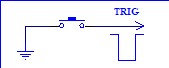
It is essential to consider the possibility of false triggering caused by switch bounce.
A.3 Pin Configuration
The interface uses a 2EDG 5.08 mm connector; the pin assignments are shown in the figure below:
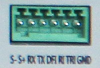
S- and S+ are used as remote inputs; please pay attention to the polarity and do not reverse the connections!
The ON and GND pins are used for external startup; do not apply any external voltage or current sources!
TRG and GND are used as trigger inputs; do not apply any external voltage or current sources!
4. Telecomanda
Main Content of This Chapter: The instrument supports data communication and remote control without the instrument panel via the RS232C serial interface, USB-CDC, or USB-TMC; however, these cannot be used simultaneously. They share the instrument’s standard SCPI command set but utilize different hardware configurations and communication protocols. This chapter describes how to use the interfaces; for details on interface commands, refer to “CH97 Programming Protocol.”
4.1 RS232C Remote Control System
The instrument’s standard RS232C interface can be used to communicate with computers and PLCs, providing the most cost-effective and convenient means for data acquisition and statistical analysis. The instrument offers a wide range of programmable commands; through the RS232C interface, a computer can perform nearly all the functions available on the instrument’s front panel.
RS-232C Bus
Although RS-232C can be completely replaced by USB communication solutions, it is still used in some industrial applications and PLC control systems, where it has a very broad user base. Standard RS-232C interfaces use 25-pin connectors (now largely obsolete) and 9-pin connectors.
Like most serial ports in the world, this instrument’s serial interface is not strictly based on the RS-232 standard, but rather provides only a minimal subset of it. As shown in the table below:
| Semnal | Simbol | Connector Pin Numbers |
| Trimite date | TXD | 3 |
| Primiți date | RXD | 2 |
| Pregătire | GND | 5 |
RS232C Configuration
This instrument uses a standard 9-pin DB connector. The image on the right shows the connection cable:
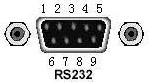
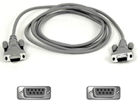
Connect to the host computer using an RS232C serial communication cable. The most basic connection setup is as follows:
TXD(2) (3) RXD
Computer M983X
(Controller) RXD(3) (2) TXD Instrument
GND(5) (5) GND
RS232C Specifications
| Metoda de transmisie | Full-Duplex Asynchronous Communication with Start and Stop Bits |
| Viteza de transmisie | 1200 bps, 9600 bps, 19200 bps, 38400 bps, 115200 bps |
| Bit de date | 8 BIT |
| Stop Bit | 1 BIT |
| Verificare | Nici unul |
| End-of-line character | CR, LF, or CR+LF (optional) |
| Informatii de contact | Software Contact |
| conectori | conector DB9 |