
 Engleză
 中文简体
中文简体 Русский
 Español
 Português
 Türkçe
 العربية
 Deutsch
 Polski
 Italiano
 Français
 한국어
한국어 ไทย
ไทย Tiếng Việt
 日本語
日本語





























Generator de câmp magnetic
Manual de utilizare
Aplicabil LISUN modele: PFM61000-8A、PFM61000-8B
1. Despachetarea și familiarizarea de bază cu echipamentul
1.1 Specificații tehnice cheie
| Numărul modelului | PFM61000-8A | PFM61000-8B |
| Puterea câmpului magnetic | Long-term: 1 A/m to 100 A/m (continuously adjustable); Short-term: 100 A/m to 1000 A/m (continuously adjustable) |
Long-duration: 1 A/m to 400 A/m (continuously adjustable) Short-duration: 400 A/m to 1000 A/m (continuously adjustable) |
| Durata câmpului magnetic | Long duration: 1 second to 999 minutes; Short duration: 1 second to 5 seconds |
|
| Total Harmonic Distortion of Output Current | ||
| Direcția câmpului magnetic | Horizontal, vertical, and 360-degree rotation in any direction, with vertical movement, to support both the proximity method and the immersion method testing | |
| Frecvența câmpului magnetic | 50 Hz sau 60 Hz | |
| Bobină de câmp magnetic | 1 x 1 m single coil | 1 x 1 m, multiple turns |
| Sistem de control | 10-inch Extra-Large Chinese-English Android Touchscreen | |
1.2 Despachetarea și verificarea conținutului
1.2.1 Despachetare și inspecție vizuală
Când despachetați dispozitivul, manipulați-l cu grijă pentru a evita zgârierea carcasei exterioare cu unelte ascuțite. După despachetare, inspectați mai întâi exteriorul dispozitivului pentru a vă asigura că nu există deformări sau lovituri evidente și că butoanele nu sunt deteriorate sau slăbite. Dacă observați anomalii la dispozitiv sau la accesoriile sale, nu îl porniți. Vă rugăm să ne contactați imediat.
1.2.2 Unitatea principală și accesoriile
Main Unit Category: PFM61000-8 Magnetic Field Generator, power-frequency magnetic field coil, and mounting bracket.
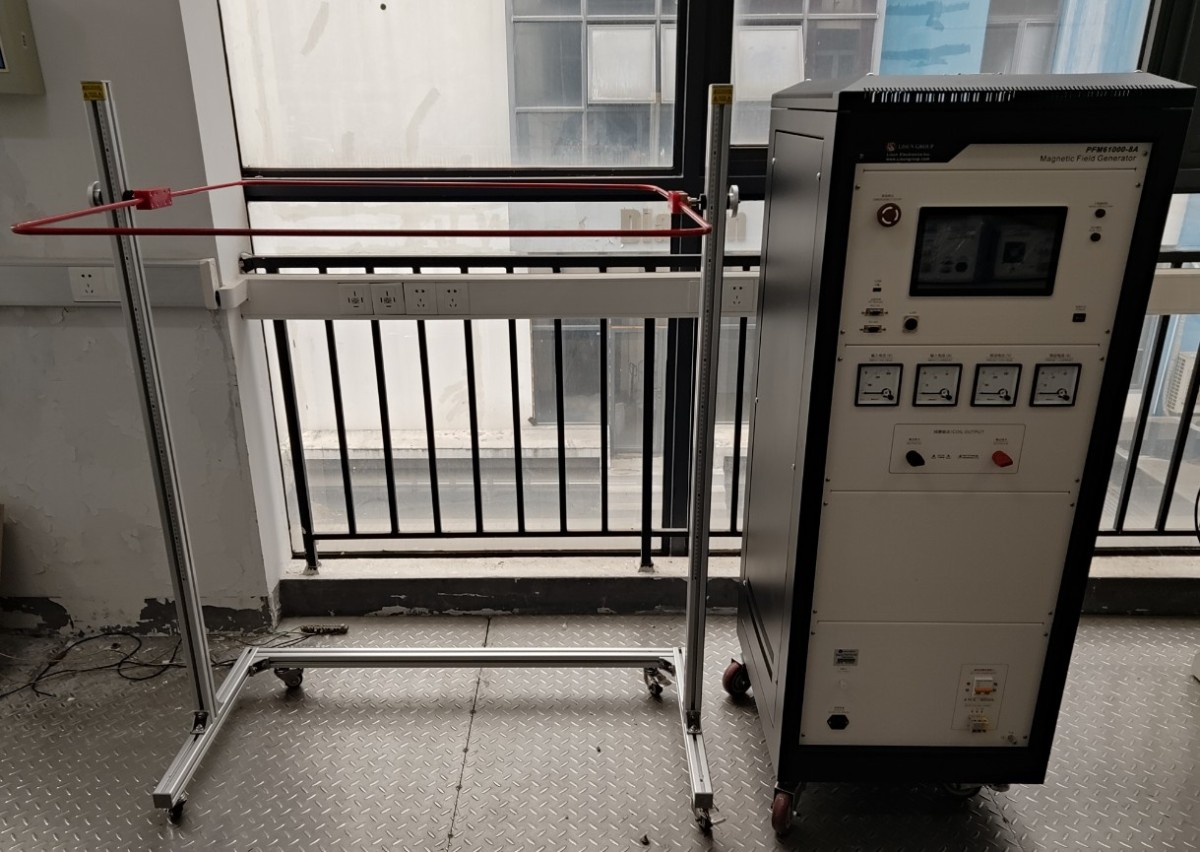
Figura 1
Other Standard Accessories:
| Număr | notițe |
| ① | Power-frequency magnetic field coil connection cable, connecting the coil to the main unit |
| ② | Power Input Connection Cable for Power Line Frequency Magnetic Field Coil |
| ③ | Cablu de alimentare |
| ④ | Cablu de împământare, utilizat pentru conectarea la terminalul de împământare de protecție PGND |
| ⑤ | Coaxial cable, which can be used to connect an external oscilloscope to view the coil current |
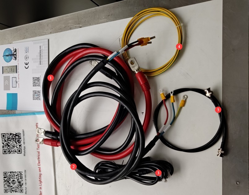
Figura 2
Download links for the digital user manual, software, warranty card, and other materials have been sent via email. Please download them promptly. If you missed the email, you may contact us to request the download links again.
1.3 Scopul principal al echipamentului
This equipment is specifically designed for power-frequency magnetic field immunity testing of electrical and electronic products. It simulates the power-frequency magnetic field environments found in residential and commercial areas, industrial and mining enterprises, power plants, and medium- and high-voltage substations, providing an accurate basis for testing the immunity performance of the equipment under test (EUT). It fully complies with the requirements of the GB/T 17626.8-2006 and IEC 61000-4-8:2020 standards.
2. Măsuri de siguranță
2.1 Ghid de plasare
Ensure the ambient temperature is between 15°C and 35°C, relative humidity between 10% and 60% (no condensation), and atmospheric pressure between 86 kPa and 106 kPa. Avoid short circuits or damage to the equipment caused by moisture;
Spațiile trebuie să fie lipsite de interferențe electromagnetice puternice, gaze corozive, materiale inflamabile sau explozive și praf și trebuie să fie bine ventilate pentru a preveni pericolele cauzate de scântei electrice;
Place on a level surface; avoid tilting or inverting the unit, and keep it away from sources of vibration;
The equipment must be placed at least 1 meter away from walls and surrounding structures (such as other testing equipment and shelving) to facilitate maintenance; at least 2 meters of space must be left in front of the equipment to ensure smooth operation, and there must be no obstructions in the surrounding area.
2.2 Specificații sursei de alimentare
Verify that the equipment’s power supply voltage matches the mains voltage (AC 220 V ±10%, 50/60 Hz), and ensure that the power supply is properly grounded and that the ground wire is not damaged or loose;
Verify that the power supply voltage for the magnetic field coil matches the supply voltage (AC 220 V ±10%, 50/60 Hz), and ensure that the power supply is properly grounded and that the grounding wire is free of damage or looseness. Note that the maximum inrush current when the coil starts up can reach 25 A to 32 A. If a ground-fault circuit interrupter (GFCI) is installed, please ensure that the GFCI’s trip current rating meets the equipment’s testing requirements;
Grounding Requirements: The host unit’s protective ground terminal (PGND) must be connected to earth, with a grounding resistance of ≤4 Ω, to ensure the safe dissipation of test voltage and current.
2.3 Proceduri de operare
Operators must undergo professional training and be familiar with this manual and the relevant standards. Non-professionals are prohibited from operating or disassembling the equipment. Opening the cover without authorization may pose an electric shock hazard; contact the manufacturer’s technical staff for repairs.
While the equipment is in operation, do not touch the terminals, wiring, coils, or samples under any circumstances.
Before testing, make sure there are no unauthorized persons in the test area, especially around the coil.
Operatorii trebuie să aibă mâinile uscate și nu trebuie să poarte bijuterii metalice.
People with implanted medical devices (such as pacemakers) should not operate this equipment to avoid any effects that strong magnetic fields may have on their implanted devices.
Before replacing the EUT, you must ensure that the test has been stopped.
Când sunt implicate mai multe persoane, definiți clar rolurile și responsabilitățile și confirmați-le reciproc înainte de a începe testul pentru a evita erorile.
2.4 Altele
Pentru aspectele care nu sunt acoperite de acest manual, vă rugăm să procedați cu prudență sau să ne contactați.
3. Equipment Hardware Overview and Wiring
| Număr | notițe |
| ① | Power-Frequency Magnetic Field Coil and Its Bracket |
| ② | Coil connection cable, connecting the main unit to the coil |
| ③ | Cablul de alimentare al computerului |
| ④ | Comutator de alimentare gazdă |
| ⑤ | Comutator de oprire de urgență |
| ⑥ | Touchscreen |
| ⑦ | Main circuit, i.e., coil input power supply indicator light |
| ⑧ | Test Indicator Light |
| ⑨ | USB port for connecting a USB mouse or a USB flash drive to update the software |
| ⑩ | The other ports here are reserved; unless otherwise specified, they are currently inactive. |
| ⑪ | Input the voltage and current readings to display the voltage and current at the coil power input terminal at point ⑬ when switch ⑭ is turned on. |
| 10 | Preset voltmeter and preset ammeter, displaying the current actual preset voltage and preset current values |
| 10 | Coil input power supply connection wire; refer to Section 2.2.1 for connecting it to a suitable power source. |
| 10 | Coil Input Power Supply Switch |
| ⑮ | You can use a coaxial cable to connect an external oscilloscope and view the coil current. |
| ⑯ | PGND: Protective ground terminal. Connect to ground using a ground wire. See Section 2.2.1. |
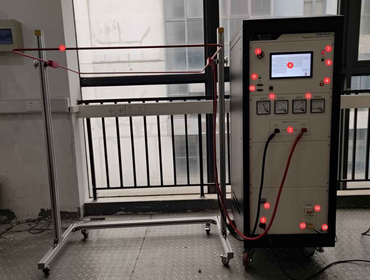
Figura 3
4. Introducere în programul cu ecran tactil
4.1 Ecranul de pornire a programului
| Număr | notițe |
| ① | General Usage Guidelines (This feature is still under development; please do not use it at this time) |
| ② | Comutați între chineză și engleză |
| ③ | Ecranul cu informații despre sistem |
| ④ | Power-Frequency Magnetic Field Test Interface |
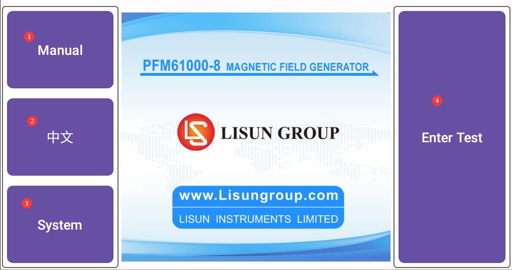
Figura 4
4.2 Power-Frequency Magnetic Field Test Interface
| Număr | notițe |
| ① | Set test field strength |
| ② | Set test duration |
| ③ | The excitation current is automatically calculated based on the set field strength; no adjustment is required. |
| ④ | Coil factors, preset parameters—no modifications required |
| ⑤ | Number of tests: Generally, one test is sufficient. |
| ⑥ | Reveniți la ecranul de pornire |
| ⑦ | Test Parameter Settings Interface |
| ⑧ | Troubleshooting Interface: No troubleshooting is required during normal use of the device. If the device produces abnormal test data in the future, please contact us for troubleshooting. |
| ⑨ | After clicking “Start,” the device will begin the self-calibration process. |
| ⑩ | Display of Power-Line Magnetic Field Frequency |
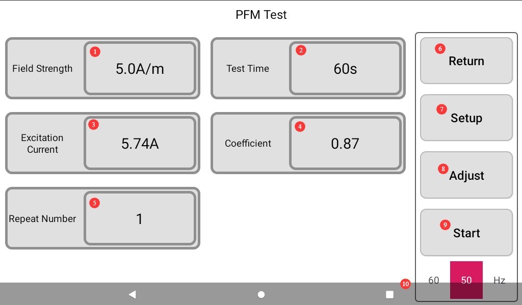
Figura 5
4.3 Test Parameter Settings Interface
| Număr | notițe |
| ① | Set the Test Field Strength |
| ② | Set the test duration |
| ③ | Set the frequency of the power-frequency magnetic field |
| ④ | Return to the Power-Frequency Magnetic Field Test Screen |
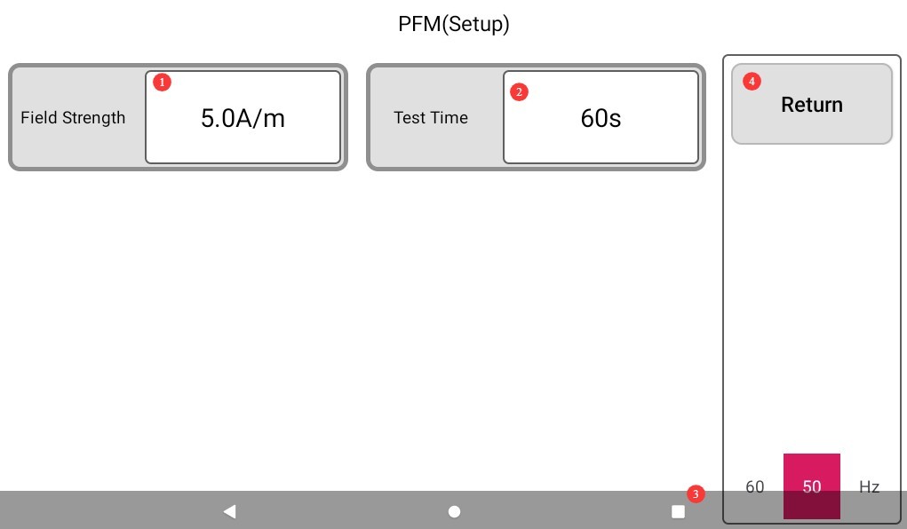
Figura 6
5. Arrangement of the EUT and Test Bench
5.1 Test Bench Requirements
The test bench must be made of non-metallic materials (such as wood or plastic) to prevent metallic materials from affecting the magnetic field distribution. The recommended height of the test bench is 80 cm to 100 cm to facilitate operation and observation of the EUT’s condition. The test bench must be placed in the center of the coil to ensure that the EUT is in a uniform magnetic field environment.
5.2 EUT Placement Specifications
In accordance with the requirements of GB/T 17626.8-2006 and IEC 61000-4-8:2020, place the EUT on the test bench in its normal operating condition. The relative position between the EUT and the coil must comply with the standard specifications (typically at the centerline of the coil) to avoid distances that are too close or too far, which could affect test accuracy. The power and signal cables connected to the EUT must be arranged according to actual usage conditions to prevent additional interference.
6. Power-frequency Magnetic Field Testing
6.1 Procedura de pornire
Refer to Chapter 3 to connect all wires properly. Turn on the main unit’s power, then turn on the coil power input switch. The coil power input indicator light will illuminate, and the coil input voltage display will show the current coil input voltage.
6.2 Magnetic Field Generator Ready
6.2.1 Setările parametrilor de testare
Set the test parameters required by the standard and the EUT performance class, as well as those specified in sections 1.1 and 4.3.
6.2.2 Host Self-Adjustment
Once the parameters are set, return to the test interface. Click “Start,” and the device will perform self-calibration. The main unit will automatically adjust the excitation current, preset voltage, preset current, and other parameters based on the field strength settings you specified. The preset voltage and current are displayed in the lower-left corner of the program.
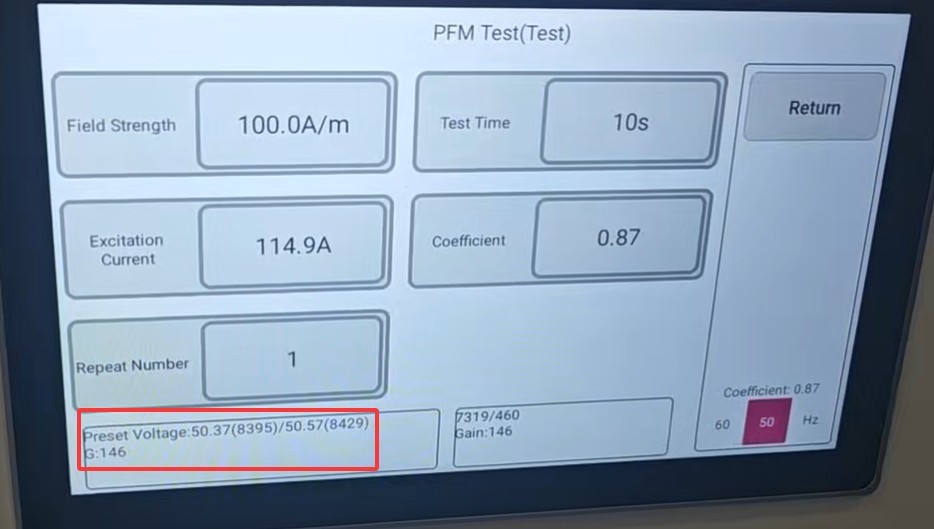
Figura 7
When the readings on the preset voltmeter and ammeter match the voltage and current values preset in the program, the main unit automatically completes the adjustment.
Note: The ammeter is a wide-range ammeter; when the actual current is low, the reading on the meter does not change significantly,
6.3 Start Testing
Once the host has finished self-calibration, the “Start” button will reappear on the program interface; click it to begin the test.
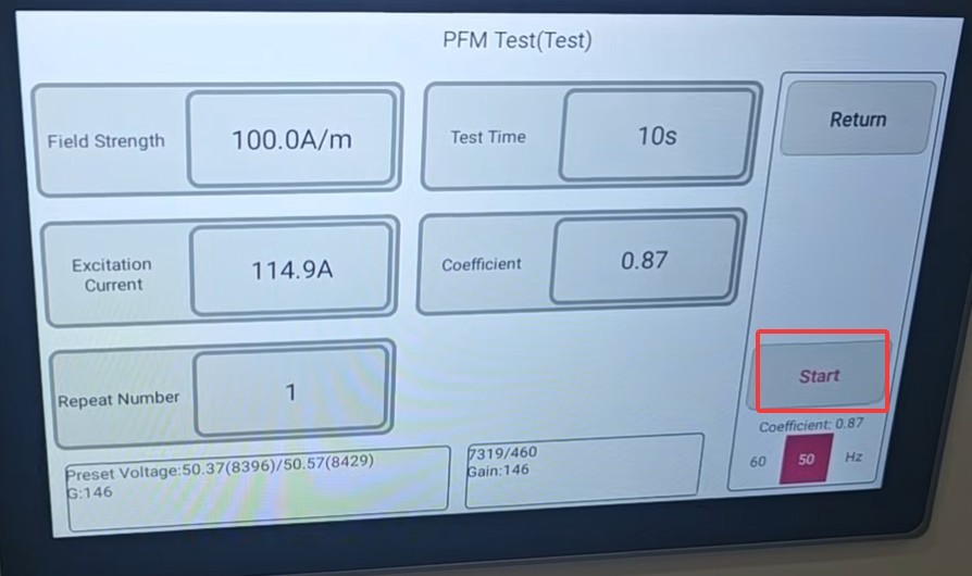
Figura 8
The host test indicator light is on.
6.4 Monitoring the Testing Process
6.4.1 Equipment Status Monitoring
| Număr | notițe |
| ① | Actual Output Field Strength of the Coil |
| ② | Actual Excitation Current Display |
| ③ | Test Countdown |
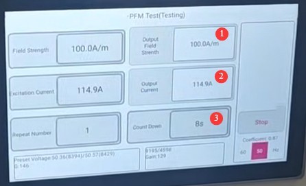
Figura 9
The output electric field strength should remain stable within ±5% of the preset value, and the excitation current should show no abnormal fluctuations. If any abnormalities occur, please stop the measurement and contact us.
6.4.2 EUT Status Monitoring
Observe and record the operating status of the EUT, including: whether it functions normally (e.g., whether it shuts down, displays errors, or experiences a decline in performance); whether the display is normal (e.g., whether indicator lights or the display screen show any abnormalities); and whether the output is normal (e.g., whether signal output and action execution meet requirements). Keep detailed records of any abnormalities observed in the EUT during the test and the time they occurred.
6.5 Evaluarea rezultatelor testelor
| Nivel | Criteriu de evaluare | Cazuri de utilizare tipice |
| A | Performance was completely normal during and after the test, in accordance with the manufacturer’s technical specifications, with no functional degradation or loss. | Precision measuring instruments, medical monitoring equipment, safety control systems |
| B | Performance may be temporarily reduced during testing, but no functionality is lost; performance automatically returns to normal after testing without requiring operator intervention. | Industrial controllers, UPS systems, and communications equipment |
| C | Functional loss is permitted during the test, but normal operation must be restored after the test through operator intervention (e.g., restarting or resetting), and the equipment must remain undamaged. | Standard office equipment, household appliances, and non-critical industrial equipment |
| D | Functionality cannot be restored after testing; the equipment is permanently damaged; or its performance fails to meet basic requirements. | Determined to be non-compliant; design corrections required |
7. Proceduri post-test
7.1 Încheierea testului
If the EUT is visibly damaged during the test, immediately tap “Stop Test” on the touchscreen. If no abnormalities occur during the test, wait for the test to end automatically.
7.2 Curățenie și organizare post-test
Turn off the input power supply on the coil, then turn off the power to the main unit.
Clean the test area and wipe it down with a dry cloth; do not use alcohol or corrosive cleaning agents.
Power-frequency magnetic field testing is a destructive test; it does not automatically generate a test report. You can create your own test report based on the recorded data and the test procedure.
7.3 Depozitarea echipamentelor
7.3.1 Cerințe privind depozitarea pe termen scurt
Dacă echipamentul este utilizat pentru operațiuni de rutină, nu este necesară nicio altă acțiune după finalizarea curățării în urma fiecărui test.
7.3.2 Cerințe pentru depozitarea pe termen lung
Dacă dispozitivul nu va fi utilizat pentru o perioadă lungă de timp (mai mult de o lună), deconectați toate cablurile și acoperiți dispozitivul cu o husă de praf pentru a preveni acumularea de praf.
The device should be powered on once a month for half an hour to prevent the aging of electrical components (such as capacitors and contactors).
8. Depanarea și rezolvarea problemelor comune
8.1 Dispozitivul nu pornește
| Simptome de eroare | Cauze posibile | Metode de depanare |
| After turning on the power switch, the device does not respond (the indicator light does not come on, and the fan does not spin). | The power cord is not properly connected or is damaged; the supply voltage is abnormal; a fuse has blown; the MOV (varistor) has failed. | Ensure that the power cord is in good condition and securely connected. Power supply issues—such as unstable voltage, excessive voltage, or harmonic interference—can cause the fuse or varistor to burn out. We recommend using a regulated, clean sine-wave AC power supply to power the equipment. If necessary, replace the fuse or varistor with one of the same type. |
The figure below shows the location of the fuse:
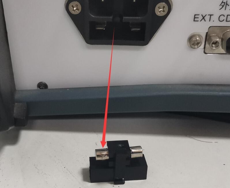
Figura 13
Figura de mai jos arată locația varistorului (MOV) în interiorul sursei de alimentare filtrate:
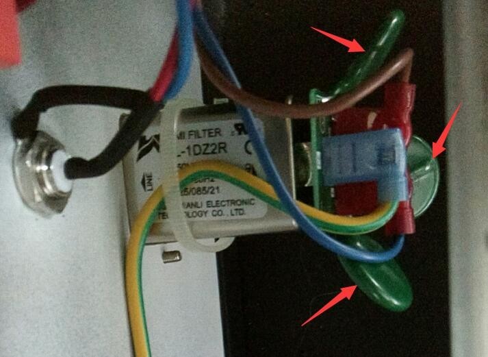
Figura 14
8.2 Circuit Breaker Tripping During Testing
| Simptome de eroare | Cauze posibile | Metode de depanare |
| After turning on the input power supply for the coil, the circuit breaker tripped in the laboratory. | The current rating of the laboratory ground-fault circuit interrupter is too low; the maximum inrush current when the coil starts up can reach 25 A to 32 A. | Upgrade the laboratory ground-fault circuit interrupter to at least 32A |