
 Engleză
 中文简体
中文简体 Русский
 Español
 Português
 Türkçe
 العربية
 Deutsch
 Polski
 Italiano
 Français
 한국어
한국어 ไทย
ไทย Tiếng Việt
 日本語
日本語





























Antena cu trei bucle
Manual de utilizare
Aplicabil LISUN modele: VVLA-30M,VVLA-30MA
1. Noțiuni de bază despre echipament
1.1 Parametri cheie
1.1.1 Clasificarea modelului
| Specificații/Numere de model | VVLA-30M | VVLA-30MA |
| Gama de frecventa | 9 kHz până la 30 MHz | |
| Dimensiuni de testare | The X, Y, and Z axes can be switched freely in the plane | |
| Specificațiile interfeței | 50 Ω/Type N | |
| Diametrul inelului | 2 m | 3 m |
| Dimensions after installation (diameter × height) | ∅2100 × 2550 mm | ∅3200 × 3750 mm |
| Metode de calibrare | Calibrated at the factory (optional ISO 17025 third-party calibration report) + Includes a calibration antenna | |
| Matching Stage | Features an integrated, height-adjustable, and expandable platform with a maximum load capacity of 50 kg | |
Notă: Acest manual folosește VVLA-30M as an example. The operation is the same for both models; the only differences are in the dimensions of the ring body and the accessories.
1.1.2 Intended Use and Applicable Standards
The VVLA series consists of three-ring vertical large-loop antennas designed for low-frequency magnetic field emission disturbance testing from 9 kHz to 30 MHz in accordance with CISPR/GB standards. They are suitable for EMC/EMI screening and type testing of LED lighting fixtures, power supplies, ballasts, and other devices.
1.2 Verificarea configurației echipamentului
1.2.1 Despachetarea
When unpacking the device, handle it gently to avoid scratching the casing with sharp tools. After unpacking, first inspect the exterior of the device to ensure there is no visible deformation or dents, and that the buttons are not damaged or loose. If you notice any abnormalities with the device or its accessories, please contact us immediately.
1.2.2 Inventory of Accessories
All equipment accessories are shown in Figure 1-1.
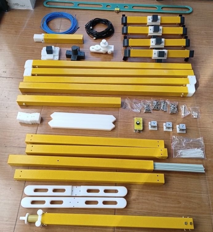
Figura 1-1
1.2.3 Descărcarea documentelor electronice
We have already sent the download links for the digital user manual, warranty card, and other documents via email at the time of shipment. Please download them as soon as possible. If you missed the email, you can also contact us directly to request the download links again.
2. Măsuri de siguranță
2.1 Specificații de împământare
Calibrate the half-wave anechoic chamber and the EMI receiver to share a common ground to avoid ground loop interference; the grounding resistance must be ≤4 Ω.
2.2 Siguranța mediului
2.2.1 Cerințe ale site-ului
Test Site: Open area / Standard semi-anechoic chamber, away from strong electromagnetic interference (inverters, arc welders, cell towers);
Ambient temperature: 10°C to 35°C; humidity: 45% to 75% RH, no condensation.
2.2.2 Cerințe de spațiu
There are no unrelated metal objects within 1.5 meters of the antenna.
2.3 Siguranța operațională
2.3.1 Cerințe de personal
Do not plug in or unplug the RF interface while it is powered on, and do not handle it with wet hands. Two people must work together during assembly and disassembly to prevent the unit from tipping over and causing injury.
2.3.2 Equipment Contraindications
Do not climb on or squeeze the antenna loop; do not force the switch open or closed. Do not operate outside the specified frequency range, and do not connect high-power transmission signals.
3. Equipment Assembly and Wiring
3.1 Calibration Antenna Assembly
3.1.1 Ansamblul bazei
Assemble and calibrate the antenna base according to Figures 3-1 through 3-3.
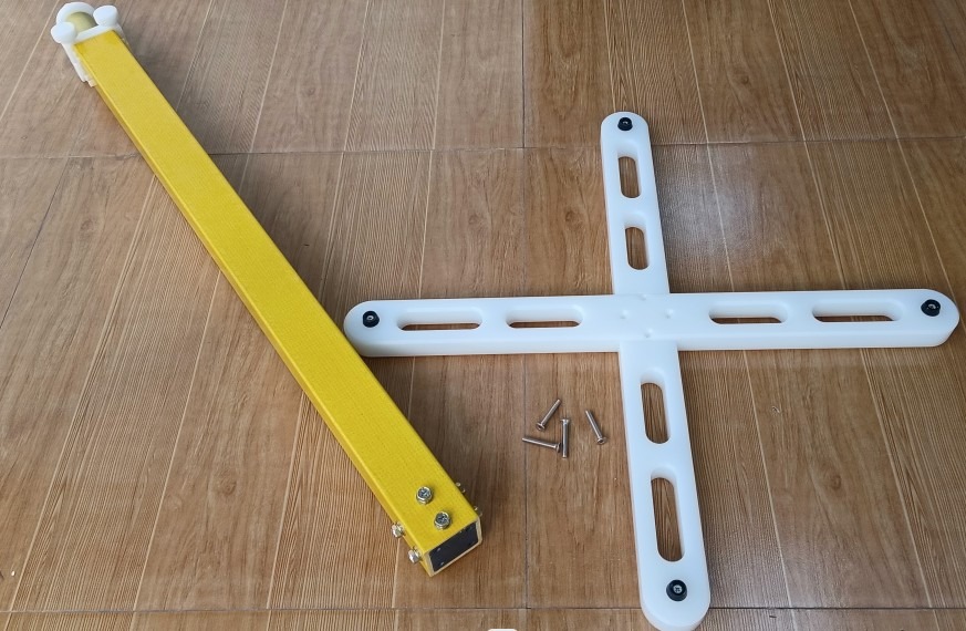
Figura 3-1
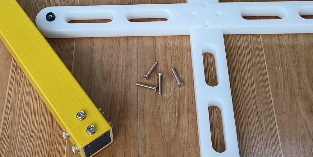
Figura 3-2
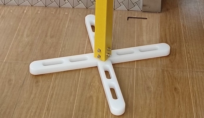
Figura 3-3
3.1.2 Antenna Assembly
Assemble and calibrate the antenna according to Figures 3-4 through 3-7.
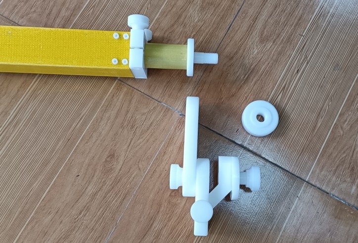
Figura 3-4
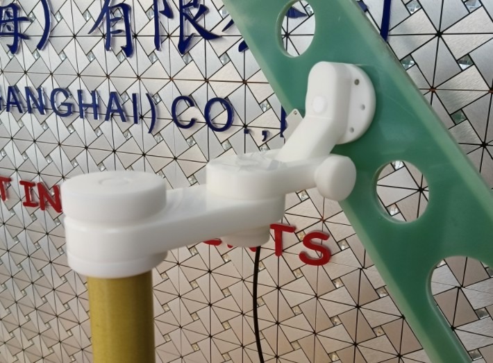
Figura 3-5
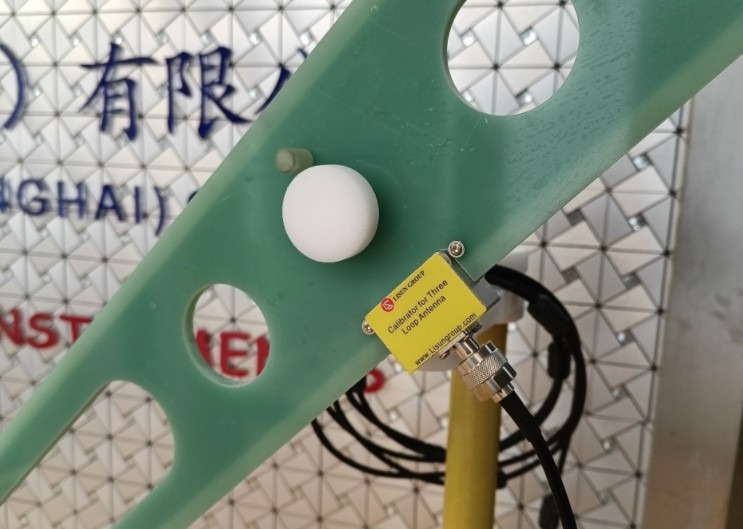
Figura 3-6
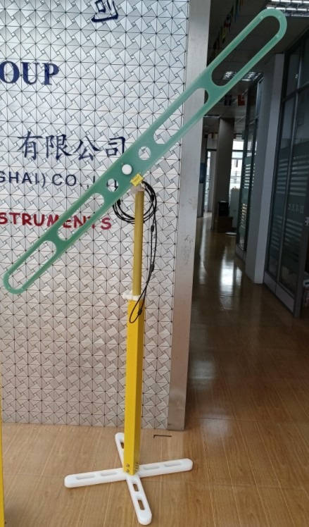
Figura 3-7
3.1.3 Scenarios for Using Calibration Antennas
As described in Chapter 4, a calibration antenna is required when calibrating the Three Loop Antenna. However, a calibration antenna is not required when performing routine testing with the Three Loop Antenna.
3.2 Assembly of The Three Loop Antenna
3.2.1 Ansamblul bazei
Assemble the Three Loop Antenna base according to Figures 3-8 through 3-12.
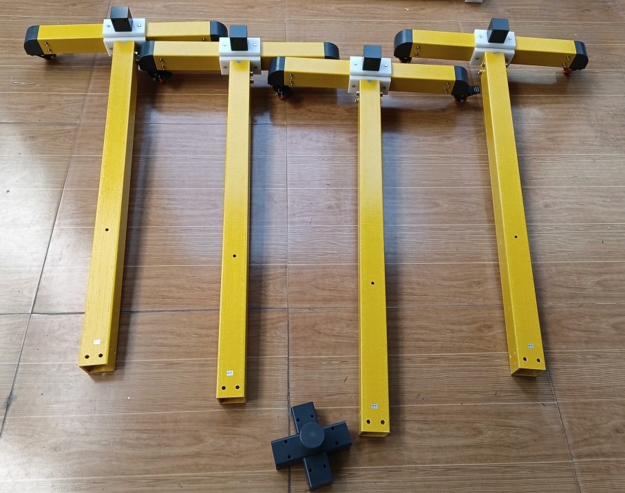
Figura 3-8
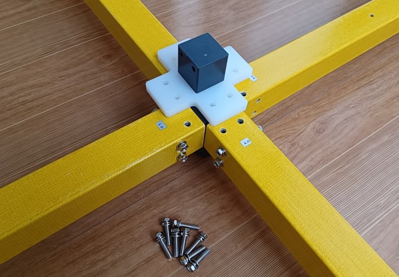
Figura 3-9
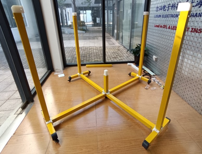
Figura 3-10
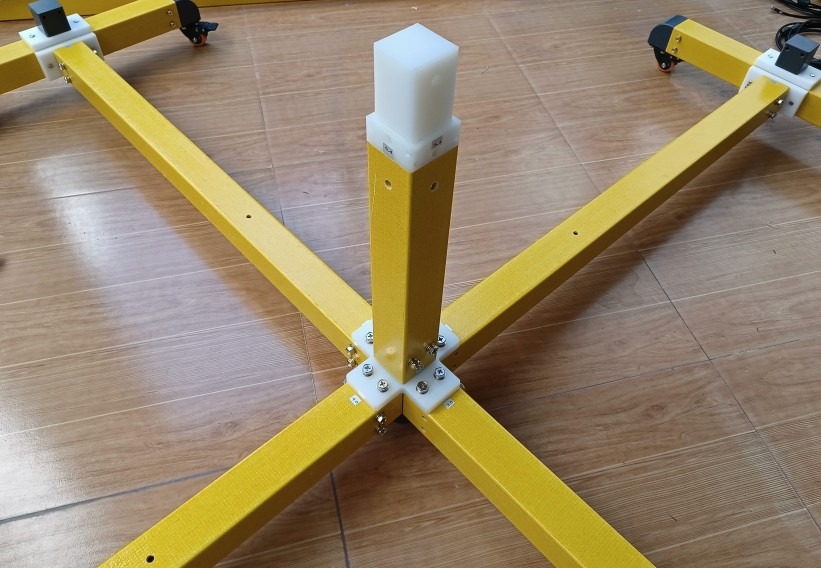
Figura 3-11
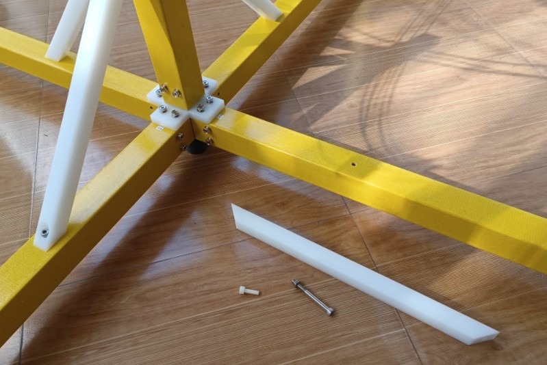
Figura 3-12
3.2.2 Three-Ring Assembly
Assemble the circular three-ring frame according to Figures 3-13 through 3-14.
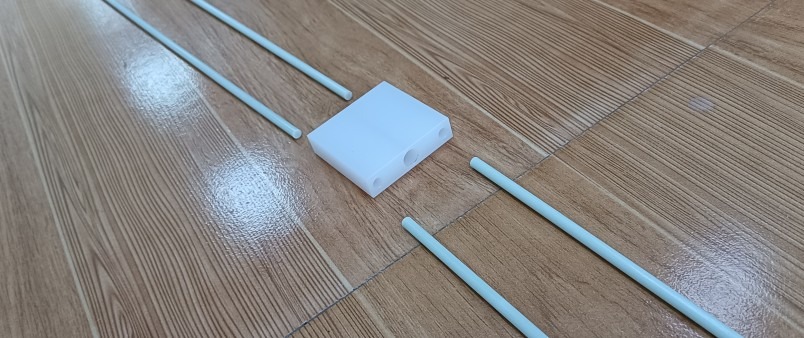
Figura 3-13
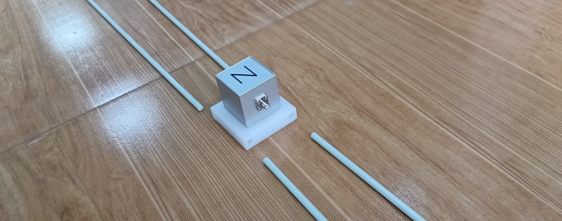
Figura 3-14
Connect the three rings end-to-end and mount them to the base. Ring X is the horizontal ring, while rings Y and Z are the vertical rings. The X, Y, and Z sensor housings must face outward and be positioned close to and connected to the corresponding X, Y, and Z ports on the XYZ signal selector switch. See Figure 3-15.
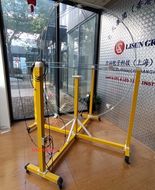
Figura 3-15
Install and connect the X, Y, and Z test leads. As shown in Figure 3-16, all marked connection points have routing holes for the test leads to pass through. Please route the X, Y, and Z test leads through the centers of the X, Y, and Z rings, respectively, and connect them securely to the X, Y, and Z sensor boxes.
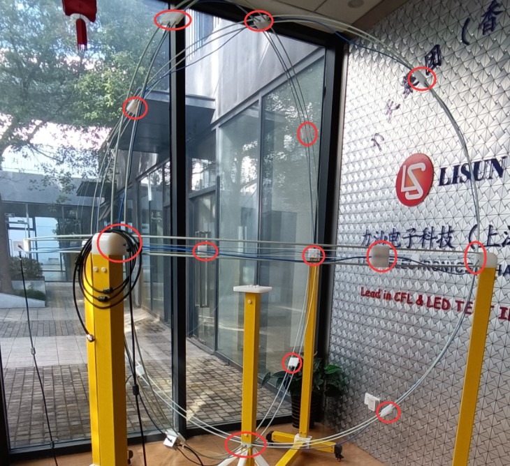
Figura 3-16
3.2.3 DUT Test Fixture Assembly
Assemble the DUT fixture as shown in Figures 3-17 through 3-18.
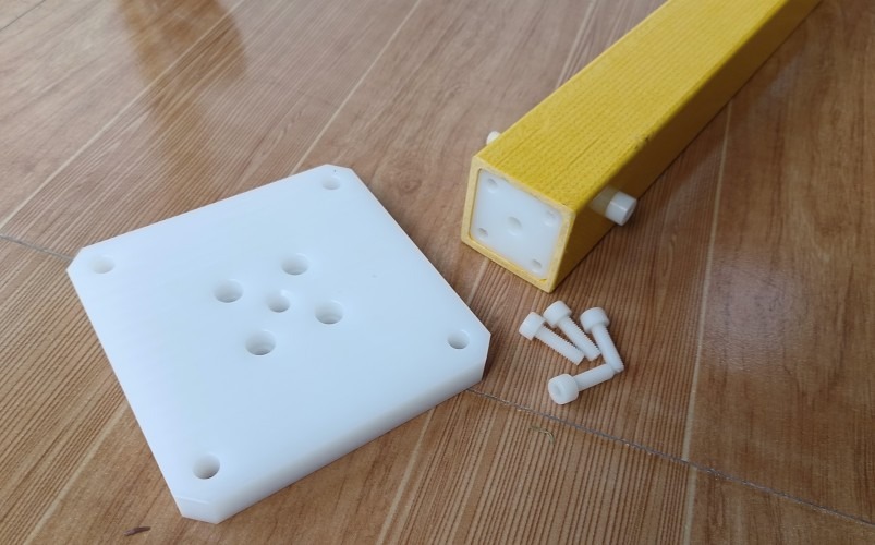
Figura 3-17
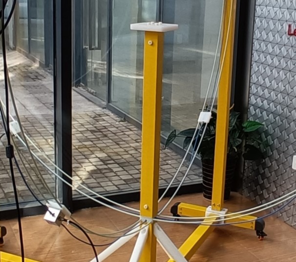
Figura 3-18
Note: The DUT stage is height-adjustable to accommodate DUTs of different sizes.
3.3 Conexiuni prin cablu
The output of the Three Loop Antenna—that is, the XYZ signal selector switch—is connected to the EMI receiver.
4. Three Loop Antenna Calibration
4.1 Calibration Prerequisites
4.1.1 Calibration Requirements
The calibration provider must be ISO 17025-accredited.
4.1.2 Calibration Conditions
The equipment has been fully assembled, and both mechanical and electrical inspections have been passed; the environment meets the required standards and is free of strong interference; all necessary accessories, including calibration antennas, standard signal sources, EMI receivers, and software, are present.
4.1.3 Interval de calibrare
It is recommended to calibrate once a year; recalibration is required after relocation or maintenance.
4.2 Calibration Antenna Connection
4.2.1 Placement of the Calibration Antenna
Place the calibration antenna at the center of the Three Loop Antenna and secure it firmly.
4.2.2 Calibration Cable Connection
Connect the calibration antenna output to a standard signal source, and connect the Three Loop Antenna output—specifically, the XYZ signal selector switch—to the EMI receiver for synchronous triggering.
4.3 Procedura de calibrare
4.3.1 Basic Calibration
Receiver settings: Frequency 9 kHz to 30 MHz; bandwidth compliant with CISPR 16-1-4; signal source outputs standard levels; calibrate the X, Y, and Z axes in sequence.
4.3.2 Switch Calibration
Switch the XYZ signal selector, repeat the measurement, and verify the consistency across all three axes.
4.4 Verification of Calibration Results
4.4.1 Evaluarea conformității
The calibration curve falls within the standard tolerance limits, with a three-axis deviation of ≤±1 dB.
4.4.2 Gestionarea excepțiilor
If calibration fails, check the connections, ring deformation, oxidation of the joints, and environmental interference factors, then recalibrate.
5. Using The Three Loop Antenna
5.1 DUT Preparation
5.1.1 Cerințe privind locația
The DUT is positioned at the geometric center of the three-ring configuration, with its center of gravity centered and no offset.
5.1.2 Dirijarea cablurilor
The DUT’s power and signal cables must be routed out at a uniform 45° angle, maintaining a distance of at least 0.4 m from any loop, and must not run parallel to or close to the loop structure.
5.1.3 Support Requirements
Use the standard DUT stage; do not use any other support frames containing metal components.
5.2 Preparations Before Testing
5.2.1 Environmental Background Testing
Turn off the DUT, measure the ambient noise, and verify that the background noise is 6 dB below the limit before proceeding with the test.
5.2.2 Equipment Warm-up
Power on the EMI receiver and the DUT and allow them to warm up for 30 minutes; testing may only begin once a stable operating state has been reached.
5.3 Procedura standard de testare
5.3.1 Three-Axis Scanning Test
Set the switch to the X-axis for a full-range scan; switch to the Y-axis for a repeat scan; switch to the Z-axis for a repeat scan.
5.3.2 Reading Data
Record the maximum disturbance values for each axis and their corresponding frequencies, and compare them to the standard limits.
5.3.3 Retesting of Anomalous Points
For frequency points exceeding the limit, change the orientation of the DUT, repeat the test three times, and record the maximum value.
6. Întreținerea și îngrijirea periodică a echipamentelor
6.1 Routine Maintenance (After Each Use)
6.1.1 Cleaning the Exterior
Wipe down the ring, bracket, and switch with a dry cloth.
6.1.2 Joint Inspection
Inspect the BNC and N connectors to ensure there is no looseness, oxidation, water ingress, or dust; if necessary, gently wipe them with anhydrous ethanol.
6.1.3 Cable Inspection
Do not subject RF cables to excessive pressure, bending, or cutting with sharp edges; they must be free of damage, creases, or signs of aging, and the shielding must be intact.
6.2 Safety During Handling and Storage
6.2.1 Manipulare
Disassemble the main unit and the bracket before moving them; do not lift and carry them as a single unit. Handle with care to avoid bumping the ring body and the switch box.
Stocare 6.2.2
Long-term storage: Store in a dry, well-ventilated, dust-free, and corrosion-free environment at temperatures ranging from -10°C to +60°C. When not in use, support the three rings from above to minimize stress-induced deformation; see Figure 6-1.
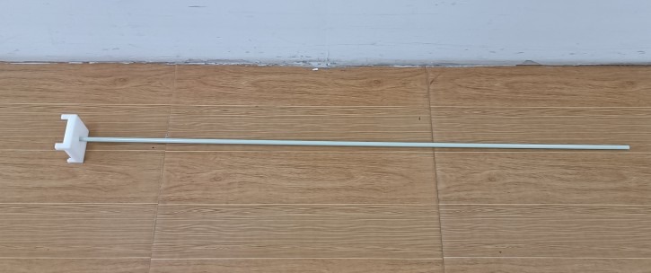
Figura 6-1
7. Depanarea și rezolvarea problemelor comune
| Simptome de eroare | Cauze posibile | Procedură |
| The EMI receiver is not receiving a signal | The frequency band setting and the XYZ signal selector switch are not in the correct position. | Check the EMI receiver settings and frequency band to ensure they are set to 9 kHz–30 MHz; check and confirm that the XYZ signal selector switch on the Three Loop Antenna is set to the correct position. |
| Excessively high background environmental noise | There is interference from other unrelated metals at the site; the test is not being conducted in an anechoic chamber; or the anechoic chamber is not grounded. | Remove all metal-containing equipment from the site; place the Three Loop Antenna and EMI receiver inside the anechoic chamber to shield them from external interference; check and confirm the ground connection of the anechoic chamber. |
| I’m not sure if the signal strength and frequency I received are accurate. | No standard signal source | We recommend purchasing a standard signal source and using it in conjunction with a calibration antenna. The standard signal source allows you to set the output signal frequency and intensity, which can then be compared with the frequency and intensity of the signal received by the EMI receiver. |