
 Engleză
 中文简体
中文简体 Русский
 Español
 Português
 Türkçe
 العربية
 Deutsch
 Polski
 Italiano
 Français
 한국어
한국어 ไทย
ไทย Tiếng Việt
 日本語
日本語





























Tester de creștere a temperaturii
Manual de utilizare
Aplicabil LISUN models: WS-8-200A、WS-8-300A、WS-8-50A
1. Noțiuni de bază despre echipament
1.1 Specificații tehnice cheie
| Număr | WS-8-50A | WS-8-200A | WS-8-300A |
|---|---|---|---|
| Stație de testare | 8 | ||
| Curent de testare | 0-50 A | 0-200 A | 0-300 A |
| Tensiunea de testare | Mai puțin de 3 V | ||
| Sistem de control | Equipped with a touchscreen display, it automatically controls the on-off sequencing and fully complies with the test requirements of Clause 19.5.1 of IEC 60884-1: 2022. | ||
| Timer | Ajustabil de la 0 la 9999 de secunde | ||
| În conformitate cu standardul | GB/T 2099.1, Clause 19 (IEC 60884-1, Clause 19) | GB/T 2099.1, Clause 19 (IEC 60884-1, Clause 19), the requirements of GB 16915.1, Clause 17 (IEC 60669-1, Clause 17), and GB/T 13140.1, Clause 15 (IEC 60998-1, Clause 15) | |
1.2 Despachetarea și verificarea conținutului
1.2.1 Despachetare și inspecție vizuală
Când despachetați dispozitivul, manipulați-l cu grijă pentru a evita zgârierea carcasei cu unelte ascuțite. După despachetare, inspectați mai întâi exteriorul dispozitivului pentru a vă asigura că nu există deformări sau lovituri vizibile și că butoanele nu sunt deteriorate sau slăbite.
If you find that the equipment or accessories are damaged or deformed, do not turn on the power. Vă rugăm să ne contactați imediat.
1.2.2 Unitatea principală și accesoriile
Temperature Rise Tester: 1 unit.
See Figure 1-1 for standard accessories.
| Număr | notițe |
|---|---|
| ① | Standard Test Model for Flush-Mounted Outlets |
| ② | Cablu de alimentare |
| ③ | Conductă |
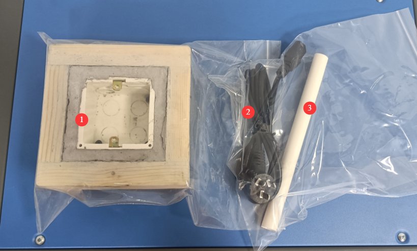
Note: The WS-8 series Temperature Rise Tester provides only high-current load output and does not include temperature acquisition or recording functions; it must be used in conjunction with a TMP series Multiplex Temperature Tester during testing.
2. Precauții pentru utilizare
2.1 Siguranta electrica
2.1.1 Conexiune la alimentare
AC 220 V, 50/60 Hz, single-phase power. Power outlets must comply with safety standards, provide proper grounding, and have a rated current that matches the equipment’s power rating and the actual load power requirements.
2.1.2 Specificații de împământare
The equipment must be properly grounded, with a grounding resistance of ≤4 Ω. Do not use gas lines, non-metallic water pipes, or the neutral wire as a substitute for the grounding wire. After grounding is complete, use a Grounding Resistance Tester to measure the grounding resistance. Power may only be applied after confirming that it meets the requirements to prevent electric shock, equipment malfunctions, or measurement errors caused by poor grounding.
2.2 Securitatea operațională
Înainte de a cabla, inspecta sau întreține echipamentul, trebuie să opriți întrerupătorul de alimentare al echipamentului și sursa principală de alimentare și să confirmați că nu există tensiune reziduală înainte de a continua;
Nu acționați comutatorul de alimentare, ecranul tactil sau butoanele instrumentului cu mâinile ude pentru a evita riscul de electrocutare;
Nu așezați obiecte străine (cum ar fi unelte sau hârtie) în interiorul tabloului de comandă electric pentru a preveni ca praful sau obiectele străine să provoace scurtcircuite sau să deterioreze componentele;
Do not plug in or unplug power cords or signal cables while the equipment is running to prevent short circuits that could damage the controller or electrical components;
The equipment is capable of outputting high currents. When connecting wires, replacing samples, or adjusting the circuitry, you must first turn off the power and set the load current control knob to the lowest setting to ensure there is no load output and to prevent electric shock;
Do not touch the sample, the thermocouple terminals, or the load output connectors during the test to avoid burns from high temperatures or electric shock;
Warning signs must be posted in the test area to prohibit unauthorized personnel from approaching and to prevent accidental contact with high-temperature samples or live electrical components.
2.3 Siguranța mediului
The equipment must be placed in a level, dry, and well-ventilated indoor environment, away from flammable and explosive materials, corrosive gases, and strong magnetic fields.
Echipamentul trebuie instalat în o cameră cu aer condiționat, cu temperatura ambiantă menținută între 5°C și 35°C și umiditatea relativă ≤ 85%.
The distance between the equipment and walls, as well as surrounding structures (such as other testing equipment and shelving), must be at least 1000 mm to facilitate operation and maintenance; cel puțin 2000 mm de space must be left in front of the equipment to ensure smooth operation, with no obstructions in the surrounding area;
3. Prezentare generală a echipamentului
3.1 Structura echipamentelor
3.1.1 Partea frontală a dispozitivului
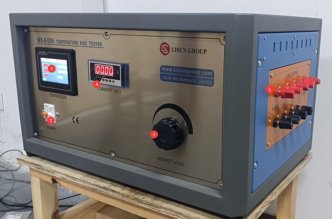
Vezi Figura 3-1.
| Număr | notițe |
|---|---|
| ① | Sample connection terminals; up to 8 samples can be connected in series at the same time |
| ② | Întrerupător |
| ③ | Test Current Adjustment Knob |
| ④ | Test Current Display |
| ⑤ | Touchscreen |
3.1.2 Partea din spate a dispozitivului
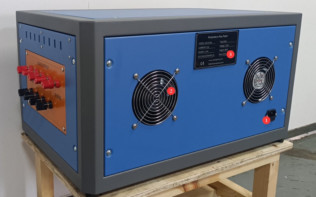
Vezi Figura 3-2.
| Număr | notițe |
|---|---|
| ① | Mufă pentru cablu de alimentare |
| ② | Ventilator răcire |
| ③ | Plăcuța de identificare a produsului |
3.2 Touchscreen Program
3.2.1 Interfață de testare
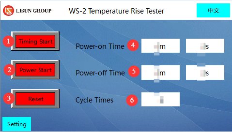
Vezi Figura 3-3.
| Număr | notițe |
|---|---|
| ① | Temporizator de pornire |
| ② | Test Power-On |
| ③ | Reseteaza |
| ④ | Sample Power-On Duration Display |
| ⑤ | Display of Sample Power-Off Duration |
| ⑥ | Repetition Count Display |
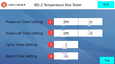
3.2.2 Parameter Settings Page
Vezi figurile 3–4.
| Număr | notițe |
|---|---|
| ① | Sample Power-On Duration Setting |
| ② | Sample Power-Off Duration Setting |
| ③ | Repetition Count Setting |
| ④ | Alarm Duration Settings |
4. Pregătiri înainte de test
4.1 Pregătirea Mediului
In accordance with the standard requirements, the test assembly should be placed in a draft-free environment during testing to prevent airflow from affecting the accuracy of temperature measurements.
When testing flush-mounted electrical accessories, a test environment that complies with the standards must be set up in advance (see the model in the “General Accessories” section): Place the mounting box into the pine groove and fill the space between the mounting box and the pine groove with plaster, ensuring that the front edge of the mounting box is flush with the front surface of the pine groove (with a deviation not exceeding ±5 mm). The plaster layer should be 10 mm to 15 mm thick, and the pine groove must be surrounded by at least 25 mm of wood on all sides; After the test assembly is constructed, it must be allowed to dry for at least 7 days.
Note: If you need models in other sizes, please contact us or manufacture them yourself according to the standards.
4.2 Confirmation of Standards Used
4.2.1 Determination of Test Parameters
Depending on the type of sample being tested, consult the corresponding standard to determine the key parameters:
| Tipul probei | Standarde de referință | Curent de testare | Durata testului | Temperature Rise Limit |
|---|---|---|---|---|
| Outlets/Plugs | GB / T 2099.1-2021 | As specified in Table 20 (e.g., for multi-outlet receptacles, use the corresponding rated current) | 60 ± 5 minute | Terminals, connectors, and clamping components ≤ 45K |
| Intrerupator | GB 16915.1-2024 | As specified in Table 17 (e.g., a test current of 20 A for a 16A circuit breaker) | 1h | Terminals ≤ 45K; non-metallic knobs/handles ≤ 5K; other non-metallic external components ≤ 55K; metallic knobs/handles ≤ 35K; other metallic external components ≤ 45K |
| conectori | GB / T 13140.1-2008 | As specified in Table 2 (e.g., 24 A test current for a 2.5 mm² connection capacity) | Reach thermal equilibrium (temperature rise ≤ 1 K within 1 hour) | Current-carrying components of the clamped part ≤ 45K |
| Note: For switches with indicator lights, if the circuit current is ≤3 mA (neon lamp/LED), temperature rise tests related to the indicator light may be omitted; when testing protective devices (such as fuses), use low-impedance wire to short-circuit them. | ||||
4.2.2 Validation of the Test Mode
Determine whether load/no-load cycle testing is required (refer to the relevant standard requirements); if cycle testing is required, specify the number of cycles, the duration of each power-on period, and the duration of each power-off period;
A TMP series Multiplex Temperature Tester is also provided to monitor the sample temperature and ensure that the placement of the thermocouple does not affect measurement accuracy (e.g., near critical areas such as clamping components or terminals).
4.3 Pregătirea unei mostre
4.3.1 Selecția și pregătirea probei
Select representative samples (such as plugs, receptacles, switches, and terminal blocks) based on test requirements, ensuring that the samples are in good condition, free of damage, and consistent with the product’s condition at the time of shipment;
Electrical accessories with detachable wiring must be connected to polyvinyl chloride (PVC)-insulated conductors with the corresponding nominal cross-sectional area as required by the standard (see the table below); accessories with non-detachable wiring shall be tested as shipped;
Nominal cross-sectional area of copper conductors used in temperature rise tests (refer to GB/T 2099.1-2021):
| Curent nominal (A) | Fixed Electrical Accessories | Portable Electrical Accessories |
|---|---|---|
| ≤ 10 | Solid/Stranded Wire, 1 mm² | Flexible wire, 1.5 mm² |
| > 10 și ≤16 | Solid/Stranded Wire 1.5 mm² | Flexible wire, 2.5 mm² |
| > 16 | Solid/Stranded Wire, 4 mm² | Flexible wire, 6 mm² |
Terminal screws or nuts must be tightened to 2/3 of the specified torque (see requirement 12.2.8 of standard GB/T 2099.1-2021).
4.3.2 Instalare exemplu
Flush-mounted outlet: Installed in a flush-mounted box, which is placed in a pine groove and filled with plaster as required. The cable enters through the top of the box, and the entry point is sealed to prevent air circulation. The length of each conductor inside the box is (80±10) mm;
Surface-mounted outlets/switches: Mounted at the center of a pine block, which must be at least 20 mm (thick) × 500 mm (wide) × 500 mm (high);
Plug: Place it in the center of a pine block (block dimensions as specified above). If the plug has a side grounding contact or a spring-loaded grounding contact, it must be inserted into a standard fixed outlet for testing;
Multiple fixed outlets (shared terminals): Insert the test plug under the most unfavorable conditions to ensure that the test current distribution meets the requirements;
Connectors: Single-pole terminals connect wires according to a predetermined method, while multi-pole terminals connect up to three adjacent terminals. Wire lengths must comply with standard requirements (1 m for wires ≤ 10 mm², 2 m for wires > 10 mm²; lengths may be shortened in accordance with the manufacturer’s specifications).
4.4 Pregătirea echipamentelor
4.4.1 Sample Connection
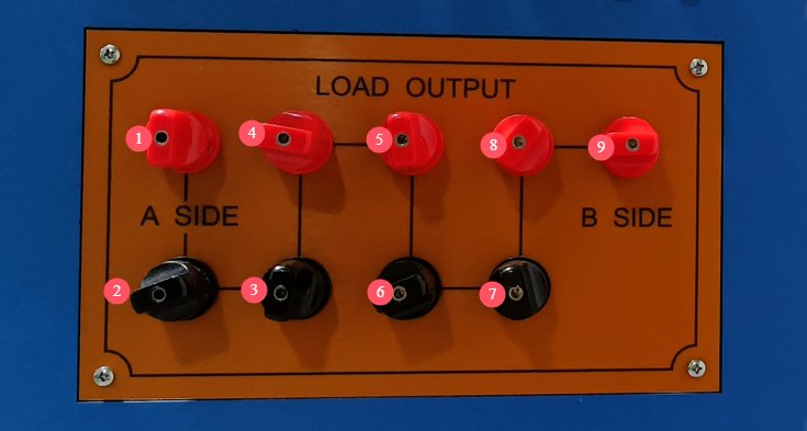
Connect them in series in the direction indicated by the black line in Figure 4-1. When the load current is high, use sufficiently thick connecting wires to ensure that the wires’ current-carrying capacity matches the test current and to prevent the wires from overheating.
If connecting only one sample, connect terminals ① and ⑨; if connecting two samples in series, connect the first sample to terminals ① and ②, and the second sample to terminals ② and ⑨; If you need to connect three samples in series, connect the first sample to terminals ① and ②, the second sample to terminals ② and ③, and the third sample to terminals ③ and ⑨. Continue in this manner.
Taking a flush-mounted outlet as an example, once all the wires are connected, it will look like the image below. You need to short-circuit the terminals to generate a test current for the circuit.
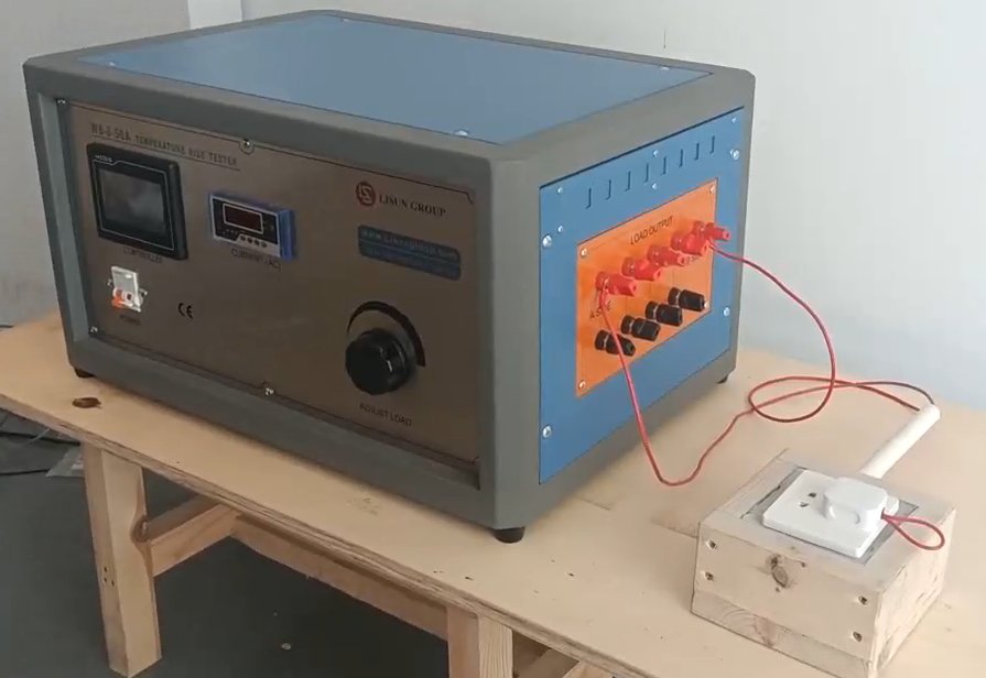
Note: Sample installation and wiring must comply with standard requirements to prevent loose wire connections that could cause poor contact or arcing.
Select the key points to be measured (such as terminals, connectors, clamping elements, and housings). Securely attach the thermocouple of the Multiplex Temperature Tester to the measurement points using high-temperature-resistant tape or adhesive (such as Loctite 7452), ensuring tight contact with the sample surface and that there is no loosening.
4.4.2 Încălzirea echipamentului
For safety reasons, first turn the test current adjustment knob on the front panel counterclockwise to the lowest setting. Then turn on the device’s power switch and let it warm up for 15 minutes before proceeding with the next steps.
5. Procedura de testare a creșterii temperaturii
5.1 Setări parametri
Refer to Section 3.2.2 to configure the required test parameters. Note: To determine whether the test requires a power-on/power-off cycle and the duration of the test, please refer to the relevant standard requirements. Once the settings are complete, return to the test interface.
5.2 Debugging, Current Testing, and Startup Testing
| Număr | notițe |
|---|---|
| ① | Tap “Test Power-On” on the touchscreen |
| ② | Turn the load current adjustment knob. Note: Adjust the current slowly to avoid sudden increases or decreases that could damage the equipment or sample. |
| ③ | Ensure that the real-time current displayed here meets the test requirements (please refer to the applicable standard to determine the specific current requirement). |
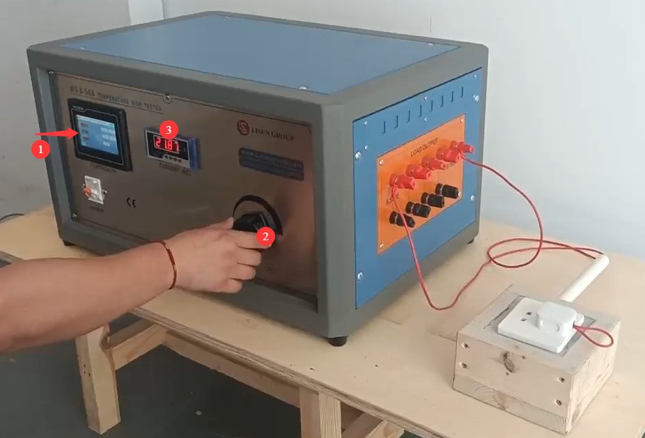
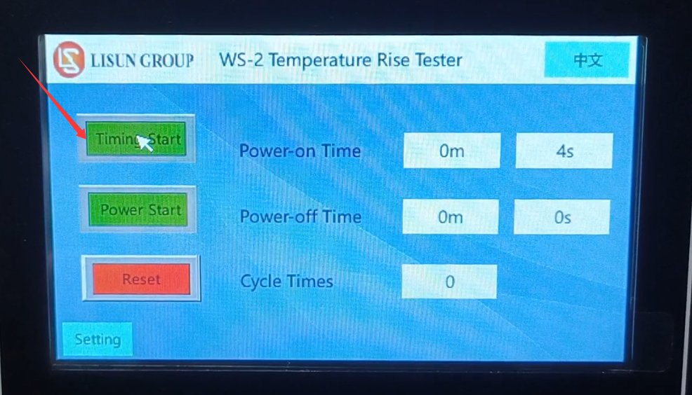
Once the test current has stabilized (fluctuation range ≤ ±0.5%), click “Start Timer” to begin the test, as shown in Figure 5-3.
5.3 Monitoring the Test Process
The Multiplex Temperature Tester software can record the initial temperature (when the power is off) and temperature changes during the test;
Monitor the load current display to ensure that the current remains stable within the test current range at all times. If abnormal current fluctuations occur, promptly investigate the cause (such as loose connections or poor contact with the sample);
If there is an abnormal spike in temperature or an alarm is triggered, stop the test immediately and investigate whether the problem lies with the sample or the equipment.
During the test, do not alter parameters, touch the wiring, or move the samples without authorization to ensure stable test conditions.
6. Proceduri post-test
6.1 Funcționarea echipamentului
6.1.1 Încheierea testului
After the test is complete, wait for the device to automatically cut off the test current, or click “Start Test Power” again to manually cut off the test current;
Tap the “Reset” button on the touchscreen to clear the data from this test and restore the device to its initial state;
Slowly turn the test current adjustment knob counterclockwise to the lowest setting, then turn off the device’s power switch.
6.2 Procesarea datelor
6.2.1 Înregistrarea datelor
Record the temperature data before and after the test (initial temperature, final temperature, and maximum temperature rise), and calculate the temperature rise using the following formula: Temperature rise (K) = Final temperature (°C) – Initial temperature (°C);
Record the test current, test duration, number of cycles (if applicable), sample model and serial number, and test environment parameters (temperature, humidity), and compile this information into a test record form.
6.2.2 Interpretarea rezultatelor
Comparison of temperature rise data from the comparative test with the standard limits:
① If the temperature rise is ≤ the standard limit, the sample is deemed to have passed the temperature rise test;
② If the temperature rise exceeds the standard limit, the sample is deemed non-compliant, and the cause of non-compliance must be analyzed (e.g., the connector sleeve is too thin, poor contact, insufficient wire cross-sectional area, etc.).
6.3 Sample and Equipment Preparation
6.3.1 Prelevarea probei
After the sample has cooled to room temperature, remove the load leads and thermocouples one by one. When removing them, avoid pulling on the wires with force to prevent damage to the sample or the thermocouples;
Inspect the condition of the sample after the test (e.g., whether it is deformed, scorched, or has loose connections) and record the relevant details.
6.3.2 Organizarea echipamentelor
Organize accessories such as thermocouples and lead wires, and store them neatly to prevent the wires from becoming tangled or damaged;
Clean the surface of the equipment (wipe with a dry cloth; do not use water), remove any debris from the test area, and keep the environment tidy.
7. Întreținere și îngrijire de rutină
7.1 Short-Term Storage Requirements
Dacă echipamentul este utilizat zilnic, nu este necesară nicio altă acțiune după finalizarea curățării în urma fiecărui test.
7.2 Cerințe de depozitare pe termen lung
Dacă dispozitivul nu va fi utilizat pentru o perioadă lungă de timp (mai mult de o lună), deconectați toate cablurile și acoperiți dispozitivul cu o husă de praf pentru a preveni acumularea de praf.
Dispozitivul trebuie pornit o dată pe lună și lăsat pornit timp de o jumătate de oră pentru a preveni îmbătrânirea componentelor electrice (cum ar fi condensatoarele și contactoarele).
8. Depanarea și rezolvarea problemelor comune
8.1 Dispozitivul nu se va porni
8.1.1 Causes of Failure
The power cord is not properly connected or is damaged; there is no power or the voltage is abnormal; the device’s fuse has blown; the power switch is malfunctioning.
8.1.2 Metode de tratament
Check that the power cord is securely connected, the plug is firmly inserted, and the power cord is not damaged; if damaged, replace it. Use a multimeter to verify that the supply voltage is AC 220 V ± 10%; if there is no power, troubleshoot the power circuit; Check whether the fuse has blown; if so, replace it with a fuse of the same specification (never substitute it with another conductor). If none of the above issues are found, the power switch may be faulty; contact the manufacturer for repair.
8.2 The current cannot be adjusted or is unstable
8.2.1 Causes of Malfunctions
The load current adjustment knob is damaged; the sample lead connection is loose or has poor contact; the Voltage Transformer is faulty; the sample is wired incorrectly or the sample itself is faulty (e.g., an open circuit).
8.2.2 Metode de tratament
Check whether the knob rotates smoothly and if there is any sticking; replace it if damaged. Re-inspect the sample wiring, tighten any loose connections, check for short circuits, and replace any damaged sample wires; Disconnect the sample wiring and short-circuit the device’s sample terminals directly. If the current still cannot be adjusted or remains unstable, the Voltage Transformer may be faulty; contact the manufacturer for repair. Check whether the sample wiring meets specifications and whether the sample is functioning properly (e.g., no open circuits). Replace any faulty samples and try again.
8.3 Inaccurate Temperature Measurement or No Display
8.3.1 Causes of Failure
The thermocouple is not properly connected or is damaged; the thermocouple is not making proper contact with the sample surface; the temperature measurement module is malfunctioning; the display shows an error.
8.3.2 Metode de tratament
Check whether the thermocouple is securely connected to the device interface; try unplugging and replugging it. If the thermocouple is broken or the insulation is damaged, replace it; Check whether the thermocouple’s sensing tip is in close contact with the sample; reattach it securely to ensure there is no play. Compare the measurement with a standard thermometer; if the deviation is too large, the temperature measurement module may be faulty—contact a calibration or repair service. If a single temperature channel shows no display, the interface for that channel may be faulty; try testing by switching to a different thermocouple interface.
8.4 Equipment Alarm Anomalies
8.4.1 Causes of Failures
Temperature rise exceeds the preset limit; test time has elapsed; abnormal current (overload).
8.4.2 Metode de tratament
If a temperature rise exceeds the limit: Immediately stop the test, check whether the sample is in good condition, verify that the thermocouple is positioned correctly, and confirm that the test parameters comply with the standard; after troubleshooting, repeat the test. If a time-out alarm is triggered: This is a normal occurrence; proceed according to the test completion procedure. If an abnormal current alarm is triggered: Check whether the current setting exceeds the rated value; after troubleshooting, reset the equipment.