
 Engleză
 中文简体
中文简体 Русский
 Español
 Português
 Türkçe
 العربية
 Deutsch
 Polski
 Italiano
 Français
 한국어
한국어 ไทย
ไทย Tiếng Việt
 日本語
日本語





























Aparat de testare cu pulverizare cu sare
Manual de utilizare
Aplicabil LISUN modele: YWX/Q-010,YWX/Q-016,YWX/Q-020、YWX/Q-022、YWX/Q-150、YWX/Q-250、YWX/Q-750
1. Unboxing and Getting to Know the Equipment
1.1 Specificații tehnice cheie
|
LISUN Model |
YWX/Q-150 |
YWX/Q-250 |
YWX/Q-750 |
YWX/Q-010 |
YWX/Q-016 |
YWX/Q-020 |
|
Studio Dimensions |
× × 600 450 400 |
× × 900 600 500 |
× × 1100 750 500 |
× × 1200 800 500 |
× × 1600 1000 600 |
× × 2000 1000 600 |
|
Dimensiunile cutiei exterioare |
× × 1100 670 1050 |
× × 1410 900 1050 |
× × 1600 1050 1200 |
× × 1700 1150 1200 |
× × 2300 1250 1450 |
× × 2800 1350 1450 |
|
Laboratory Volume |
108L |
270L |
412L |
480 |
960L |
1200 |
|
Capacitatea rezervorului de saramură |
15 |
25 |
30L |
32L |
40L |
45L |
|
Alimentare electrică |
Single-phase AC 220 V/50 Hz (60 Hz available upon request) |
Three-phase AC 380 V/50 Hz (60 Hz available upon request) |
||||
|
1.5 kW |
2.0 kW |
3.5 kW |
3.5 kW |
5.0 kW |
6.0 kW |
|
|
Space for displaying samples |
× × 500 300 250 |
× × 800 450 250 |
× × 900 600 300 |
× × 1000 600 300 |
× × 1400 800 350 |
× × 1800 800 350 |
|
How to Open the Lid |
Manual |
Manual |
Manual |
Stainless Steel Gas Springs |
Cilindru |
Cilindru |
|
Metoda de pulverizare |
Continuous, Intermittent, and Programmable Testing |
|||||
|
Tipul testului |
Neutral Test (NSS), Acid Test (AASS), Copper-Accelerated Salt Spray Test (CASS) |
|||||
|
Rack de mostre |
One set each of V-grooves and O-shaped rods (combined to form an angle of 20° ± 5°); customization available for special samples; load capacity configured based on actual conditions |
|||||
1.2 Despachetarea și verificarea conținutului
1.2.1 Despachetare și inspecție vizuală
When unpacking the equipment, handle it gently to avoid any impact on the main unit. After unpacking, first inspect the equipment housing, the glass door of the mist chamber, the touchscreen, and other components for any damage, deformation, or scratches.
Check all equipment connections (power connection, air intake, exhaust, drain, etc.) to ensure they are in good condition and free of looseness, blockages, or damage.
If you discover that the equipment or accessories are damaged or deformed, do not turn on the powercontact LISUN serviciu pentru clienți imediat.
1.2.2 Host-type
1 Salt Spray Test Machine unit.
1 air compressor. Note: This can be purchased from LISUN or procured independently. If procuring independently, refer to the following specifications: air tank capacity 55 L; air flow rate 0.6 m³/min; maximum pressure: 0.8 MPa. The air compressor must be equipped with an oil-water separator to prevent oil and moisture in the compressed air from entering the equipment’s air lines, which could cause nozzle clogging or component corrosion.
1.2.3 Consumabile și accesorii
① Graduated cylinder; ② Sample rack, V-notch, and O-shaped rod; ③ Test salt: analytically pure sodium chloride, 500 g × 2; once used up, you may purchase more on your own or contact LISUN Customer Service; ④ Spare quartz glass nozzle.
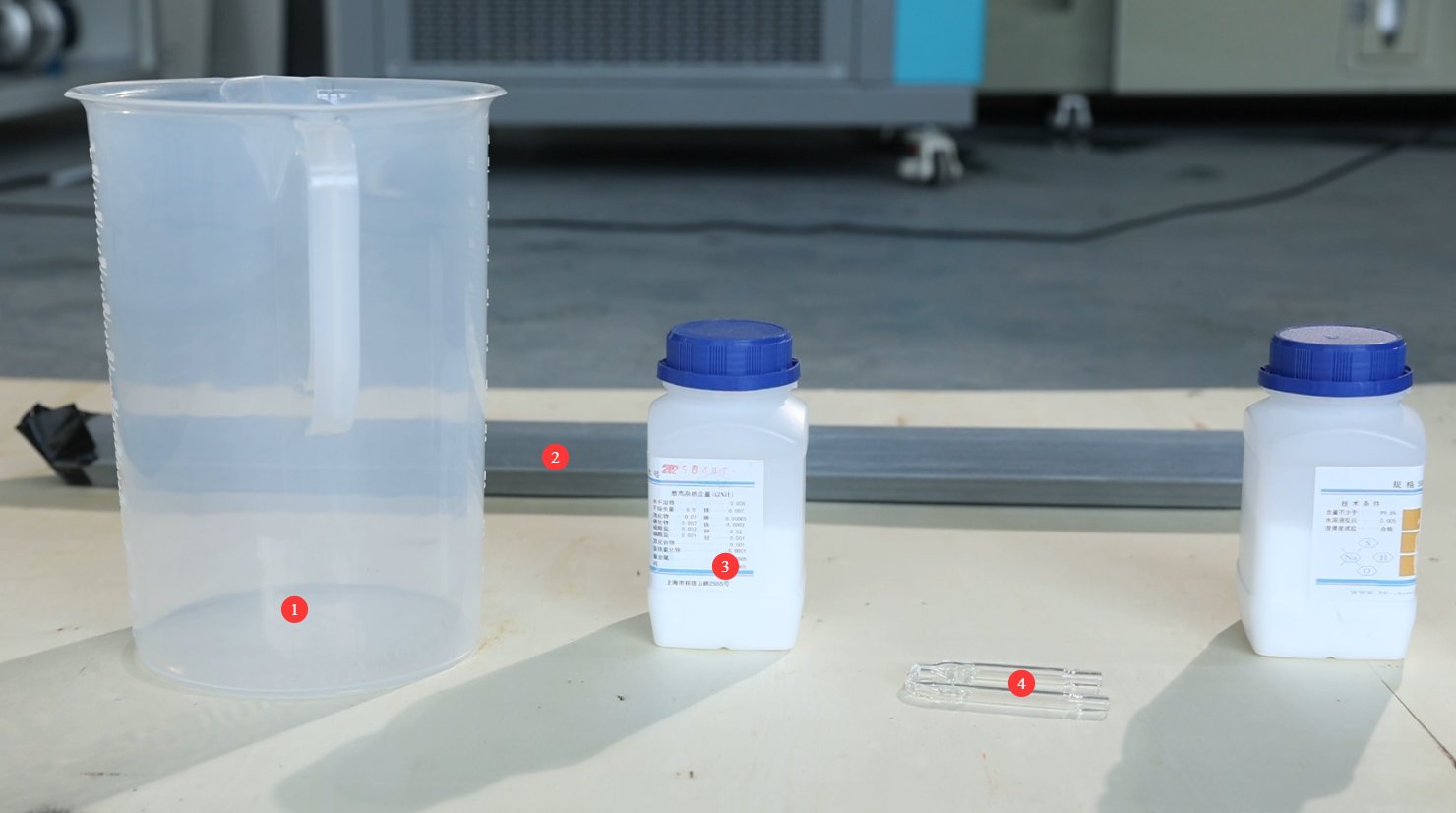
V-au fost trimise prin e-mail linkurile de descărcare pentru manualul de utilizare digital, cardul de garanție și alte documente. Vă rugăm să le descărcați cât mai curând posibil. Dacă ați pierdut e-mailul, nu ezitați să ne contactați pentru a solicita din nou linkurile de descărcare.
1.3 Descrierea structurii echipamentului
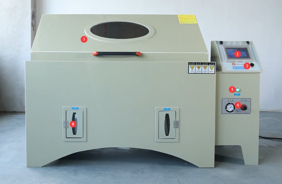
1.3.1 Front View of the Test Chamber
① Touchscreen; ② USB port, used to export test curves; ③ Power switch; ④ Spray pressure regulating valve and spray pressure gauge; ⑤ Test chamber lid; ⑥ Small graduated cylinders, connected to the mist collector inside the test chamber; the number of small graduated cylinders depends on the size of the test chamber.
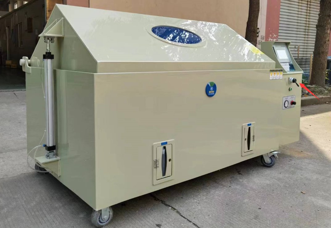
If your test chamber uses a pneumatic cylinder to open the lid, there will be a handle to control the opening and closing of the lid, as shown in the figure below:
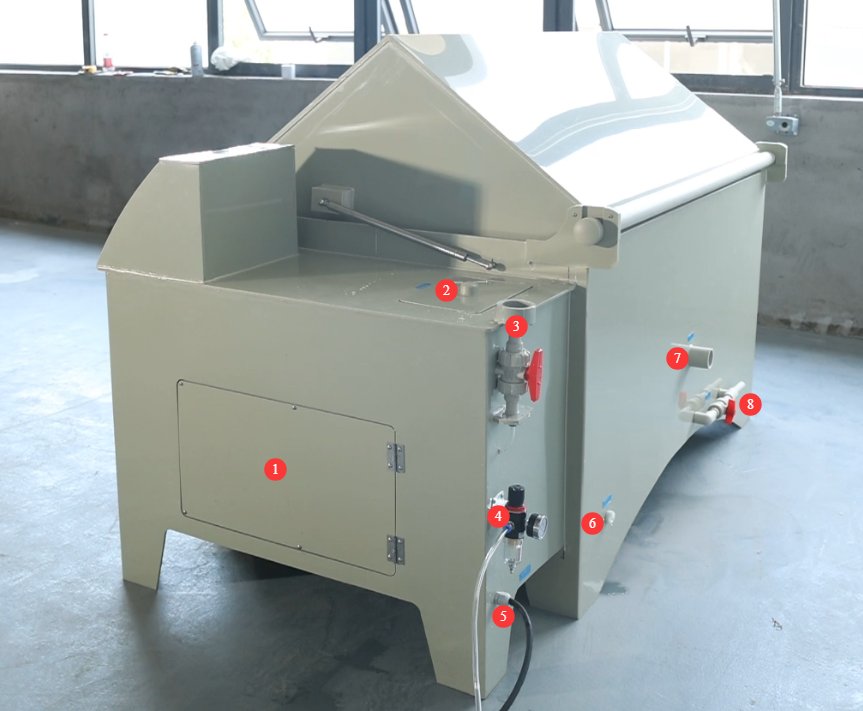
1.3.2 Sides and Back of the Test Chamber
① Electrical cabinet cover—can be opened for maintenance in the event of a malfunction; ② Brine tank; ③ Manual water inlet for the saturation tank (pressure tank);④ Air compressor connection and inlet pressure regulator (if your test chamber uses a pneumatic cylinder for opening the lid, there will be two pressure regulators); ⑤ Power cord; ⑥ Automatic water refill port, used to automatically refill the test chamber and the saturation tank; ⑦ Mist exhaust port; ⑧ Drain pipe.
1.3.3 Inside the Test Chamber (Fog Chamber)
① Brine level control device; ② Spray tower and nozzles; the number of spray towers and nozzles depends on the size of the test chamber; ③ Brine hose and saturated tank hose; these hoses contain filters that require cleaning over time; ④ Brine tank drain valve; the tank must be drained if the equipment is not used for an extended period;⑤ Demister air inlet; compressed air from the air compressor enters the test chamber through this inlet during the demisting process; ⑥ Automatic water replenishment hose for the test chamber; this must be submerged in the water at the bottom of the test chamber; ⑦ Temperature control probe; ⑧ Condensate collector; used to measure salt spray deposition; the number of condensate collectors depends on the size of the test chamber.
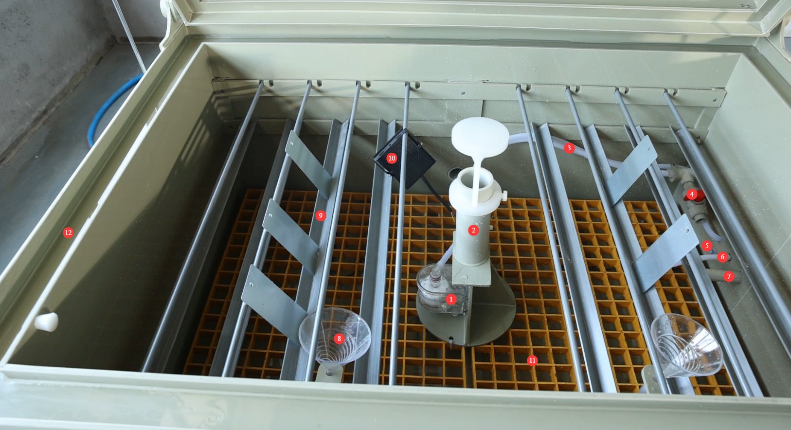
Note: If your test chamber uses a pneumatic cylinder to open the lid, you must turn on the power and the air compressor and use the cylinder to open the lid before you can see inside the test chamber.
2. Măsuri de siguranță
2.1 Siguranța electrică
2.1.1 Conexiune la alimentare
Small models (YWX/Q-150, YWX/Q-250): 220 V single-phase power, 2.0 kW power rating; requires a single 1.5 mm² wire;
Medium-sized models (YWX/Q-750, YWX/Q-010): 220 V single-phase power, 3.5 kW power rating; requires a single 2.5 mm² wire;
Large models (YWX/Q-016, YWX/Q-020): 380V, three-phase, five-wire system; power rating greater than 5 kW; wire size must be 2.5 mm² per conductor.
Power outlets must comply with safety standards, provide proper grounding, and have a rated current that matches the device’s power rating (it is recommended to install a dedicated circuit breaker).
2.1.2 Specificații de împământare
Grounding must be performed in accordance with the three-level grounding standards, with a grounding resistance of ≤50 Ω. A dedicated grounding wire (with a cross-sectional area of at least 2.5 mm²) must be used to connect to the ground.
It is strictly prohibited to connect a ground wire to gas pipes, non-metallic water pipes, heating pipes, or other flammable or explosive facilities to avoid the risk of electric shock or fire.
2.1.3 Contraindicații pentru procedură
Before wiring, servicing, or replacing parts on the equipment, you must disconnect the power supply before proceeding.
Do not touch the power connector, touchscreen, or other electrical components with wet hands. Keep the area around the device free of standing water to prevent electric shock.
If any abnormalities occur while the equipment is running—such as electrical leakage, unusual noises, or smoke—immediately disconnect the power supply and contact a professional for repairs. Do not attempt to disassemble the equipment yourself.
2.2 Siguranța operațională
2.2.1 Cerințe privind specimenele de testare
This device is intended only for testing non-flammable, non-explosive, and non-radioactive solid or flexible materials (such as metal coatings, plastic parts, and electronic component housings).
If the sample contains volatile components (such as organic solvents or corrosive gases), you must consult the equipment compatibility instructions in advance or conduct a small-scale preliminary test to confirm that there are no safety risks (such as corrosion of equipment components or the generation of toxic gases); otherwise, the sample must not be placed in the equipment.
2.2.2 Properly Connect the Exhaust Pipe
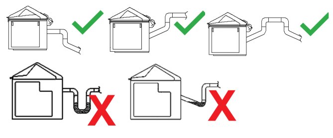
Salt spray is corrosive; the exhaust pipe must be connected to the outdoors or a dedicated sewer system. It must not be discharged indoors or connected to a standard sewer system.
The mist exhaust pipe must remain unobstructed, free of kinks or blockages, and must not include a P-trap; otherwise, salt spray condensate will accumulate inside the pipe, blocking the exhaust passage and affecting test results and equipment safety. See the diagram below:
2.2.3 Conduită interzisă
While the equipment is in operation, non-professionals are prohibited from disassembling or repairing it. In the event of a malfunction, contact after-sales service personnel or follow the instructions of a technician.
If the equipment triggers an alarm, immediately stop the test and troubleshoot the problem (see “Chapter 6: Troubleshooting and Resolution of Common Problems”). Do not force the equipment to restart; operating the equipment before the problem is resolved may cause further damage.
Do not open the test chamber lid until the test is complete and the defogging process is finished, to prevent direct contact between the salt spray and human skin.
Do not disassemble core components such as nozzles, temperature probes, heating elements, and liquid level sensors without authorization. Do not modify the equipment’s electrical, pneumatic, or structural systems. Failure to comply will void the warranty and may result in safety incidents.
2.3 Siguranța mediului
2.3.1 Cerințe de instalare
Ambient temperature: 5–25°C. Avoid excessively high temperatures, which can affect the stability of the test chamber’s temperature control, and excessively low temperatures, which can affect heating efficiency.
Relative humidity: ≤85% RH. The environment must be dry to prevent short circuits in the equipment’s electrical components caused by moisture.
Other Requirements: No direct sunlight (to prevent temperature fluctuations in the salt spray chamber); no strong electromagnetic fields (such as those from Voltage Transformers or large electric motors, to avoid interfering with the control system); no strong air currents (such as direct airflow from air conditioning vents, which can affect salt spray distribution); atmospheric pressure range: 86–106 kPa.
2.3.2 Cerințe de spațiu
The equipment must be placed on a level surface; use a level to ensure the unit is stable (tilting can cause uneven salt spray distribution and liquid leaks).
Allow sufficient space around the equipment: ≥1500 mm on the left, right, and rear sides (to facilitate piping and cabling connections, liquid refills, and maintenance), and ≥2000 mm in front (to allow for opening the control panel door and operating the touchscreen).
2.4 Altele
Pentru aspectele care nu sunt acoperite de acest manual, vă rugăm să procedați cu prudență sau să ne contactați.
3. Preparations Before Operation
3.1 Cable Duct Connections
3.1.1 Conectarea cablului de alimentare
Vezi 2.1.
3.1.2 Exhaust Pipe Connection
Use the exhaust hose provided by LISUN. If you are supplying your own exhaust hose, please use a flexible hose with an inner diameter of 50 millimeters and connect it as described in Section 2.2.2.
3.1.3 Drain Pipe Connections
Use a non-metallic pipe with an inner diameter of 20 mm (such as a PPR pipe); connect one end to the drain outlet on the back of the unit and the other end to the sewer line. The pipe must be installed at an angle to ensure smooth drainage.
3.1.4 Connecting the Automatic Water Inlet
The automatic water refill port automatically refills the saturation tank and test chamber during the test. You must provide your own piping and other accessories, and ensure that the water supply pressure is ≥0.1 MPa. If the port is not connected, you can refill the tank manually without affecting the operation of the equipment.
3.1.5 Air Compressor Connection and Inlet Pressure Adjustment
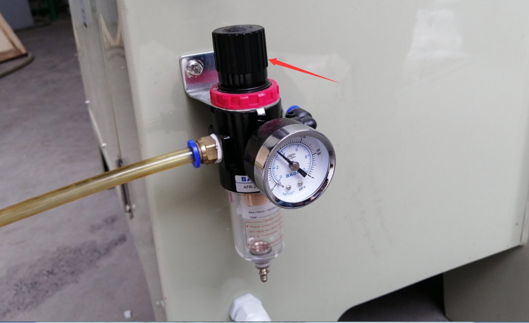
Use an 8-mm-diameter air hose, connecting one end to the air compressor’s outlet and the other end to the air inlet on the back of the device. Adjust the knob shown in the figure below to set the air pressure to 0.2 MPa for spraying.
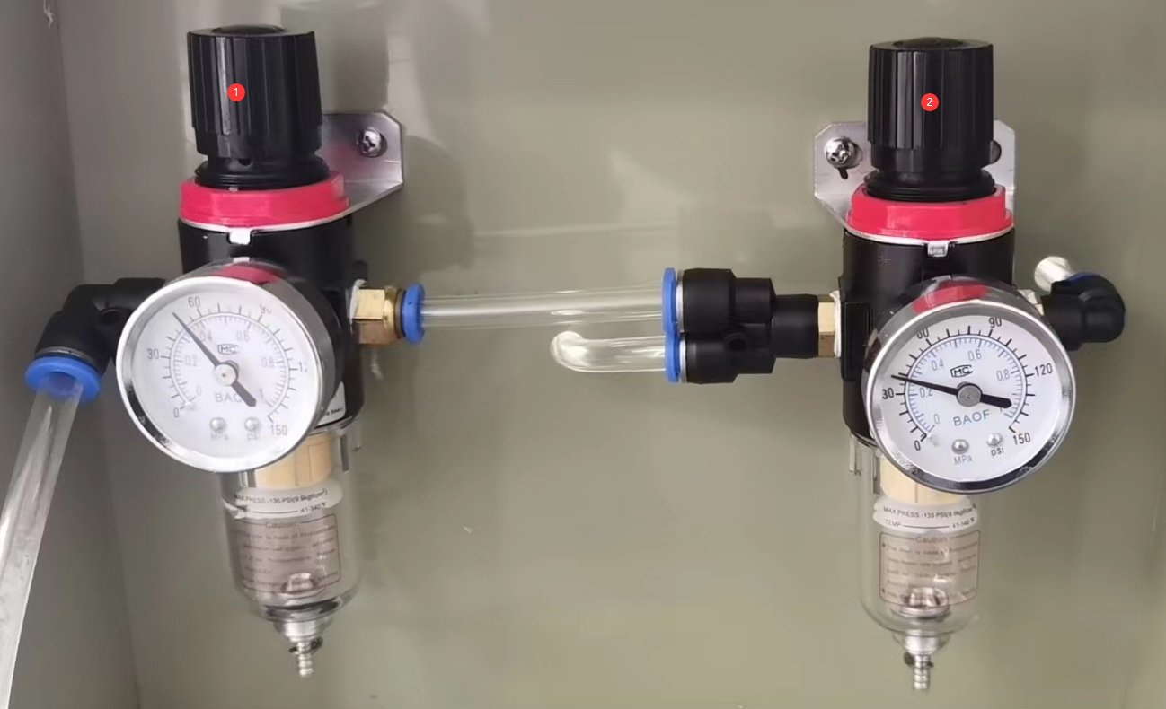
If your salt spray chamber uses a pneumatic cylinder to open the lid, there will be two pressure regulators, as shown in the figure below: ① The first one supplies air to the cylinder and should be set to 0.4 MPa. ② The second one is for the spray and should be set to 0.2 MPa.
After making adjustments, monitor the system and ensure that the air pressure remains stable; unstable air pressure can affect the spraying performance.
3.2 Checking the Test Chamber Status
3.2.1 Cleaning the Test Chamber
During transportation, debris or dust may inevitably enter the test chamber. Before using the unit for the first time, please clean the interior of the test chamber and the brine tank with clean water. Once everything has been thoroughly cleaned and the cleaning water has been drained, ensure that the equipment’s drain valve and the drain valve on the brine tank inside the test chamber are both closed.
3.2.2 Turn on the test chamber and check the water level in the water supply.
For information on touchscreen operation and functions, please refer to Chapter 4. When adding water to the water source, be sure to check the water level. Upon startup, the test chamber may trigger a low-water alarm; this alarm will clear once the water source is fully filled.
3.3 Adăugarea apei
3.3.1 Filling the Test Chamber (Fog Chamber) with Water
Open the test chamber door on the front of the unit (for small units, open the lid manually; for large units, operate the lever to activate the cylinder and open the lid automatically). Pour purified water directly into the bottom of the test chamber until the float-type level sensor rises, and the “Laboratory” water level indicator bar on the touchscreen no longer displays the red “L” low-water alarm.
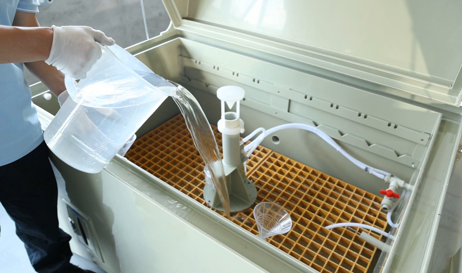
The bottom of the test chamber is equipped with an overflow outlet. If too much water is added, the excess water will drain out through the overflow outlet. The overflow outlet shares the same outlet as the drain pipe, but it is not controlled by the drain pipe valve.
If you have connected purified water to the “automatic water refill port,” the system will automatically refill the test chamber when water levels are low after the equipment is turned on or during testing.
3.3.2 Manual Water Addition to the Saturation Tank
Open the red valve at the manual fill port of the saturation tank and pour in purified water directly (do not use tap water or bottled water to prevent scale buildup). Observe the “Saturation Tank” water level indicator on the touchscreen; it will change from an “L” low-water alert to an “H” low-water alert, and then the low-water alert will disappear. When the “Saturation Tank” displays an “H” low-water level, it can still support 2–3 days of continuous testing; when the “Saturation Tank” displays an “L” low-water level, testing will be temporarily suspended, and water must be replenished immediately.
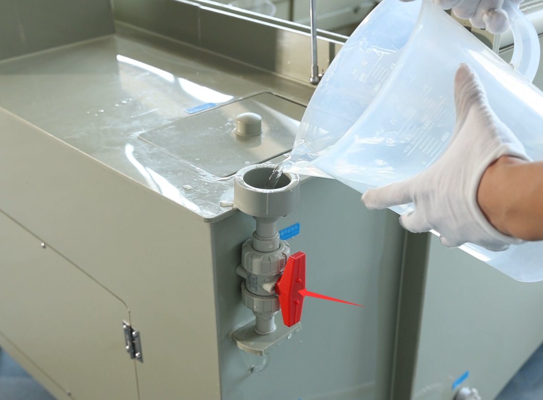
After manually adding water, be sure to close the valve; otherwise, high-pressure water will spray out during the test.
If you have connected purified water to the “automatic refill port,” the system will automatically refill the saturated tank when it runs low on water after startup or during testing.
3.3.3 Filling the Sealing Trough with Water
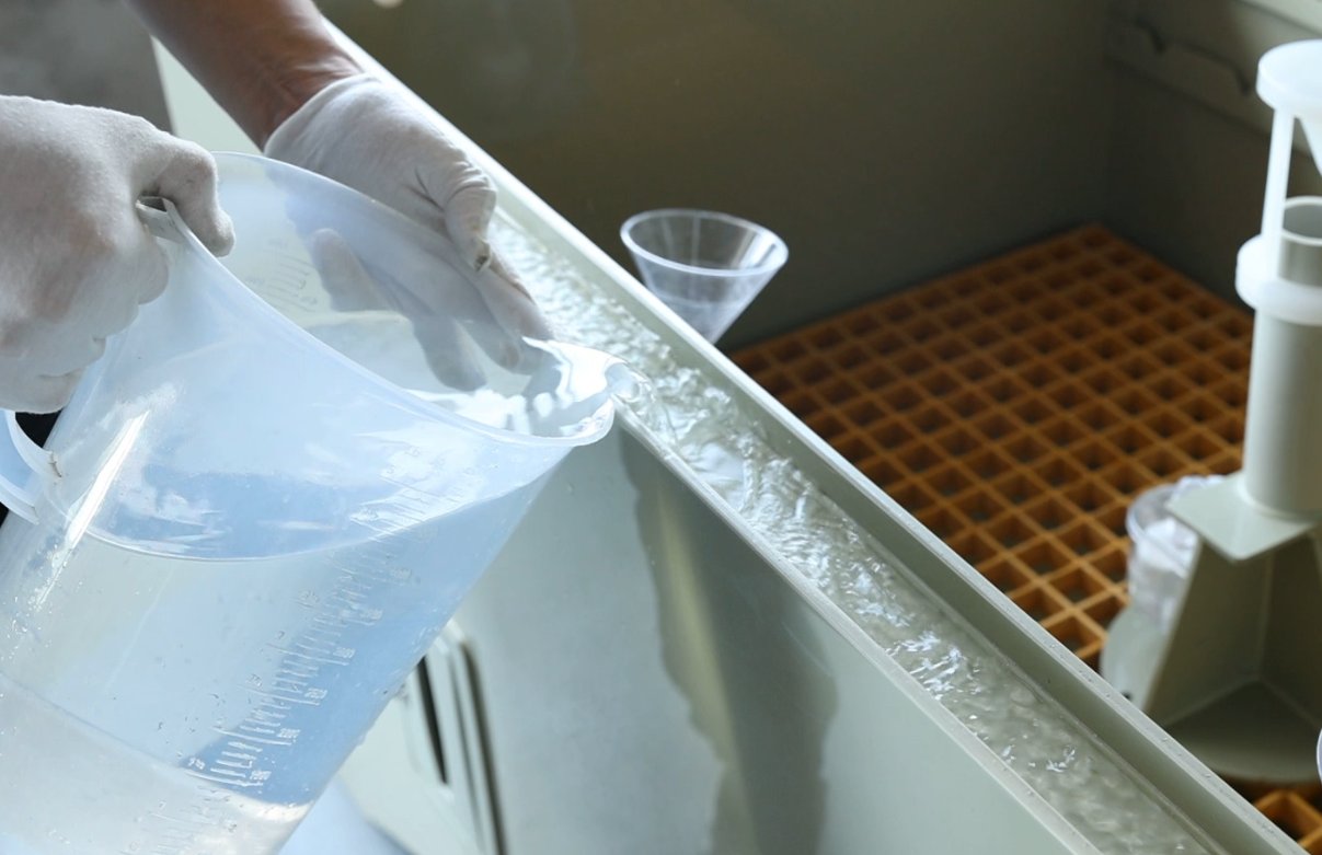
A sealing water trough is installed around the perimeter of the test chamber lid. Fill the trough with clean water to a level 2–3 cm above the bottom of the trough to ensure that the test chamber remains airtight once the lid is closed, preventing salt spray from leaking through gaps in the lid during the test.
3.4 Preparation and Injection of Saline Solution
3.4.1 Selection and Preparation of Salt Solution Concentration
In accordance with the test standard requirements, select the appropriate salt spray type and prepare the solution. Common types are as follows:
|
Types of Salt Spray |
Standarde aplicabile |
Metoda de pregătire |
Note importante |
|
Pulverizare salină neutră (NSS) |
GB/T 10125, ISO 9227 |
500 g analytical-grade sodium chloride + 9500 mL purified water; stir until the sodium chloride is completely dissolved, resulting in a 5% solution |
Sodium chloride must be completely dissolved, with no sediment; purified water must meet the Grade 1 water standard specified in GB/T 6682. |
|
Acid Salt Spray (AASS) |
GB/T 10125, ISO 9227 |
Slowly add glacial acetic acid to the NSS solution, and use a pH meter (or pH paper with an accuracy of 0.1) to adjust the pH to 3.0–3.1. |
Glacial acetic acid is corrosive; gloves and safety goggles must be worn, and it should be added drop by drop to prevent splashing. |
|
Copper-Accelerated Salt Spray (CASS) |
GB/T 10125, ISO 9227 |
Add 0.26 g/L of anhydrous copper(II) chloride to the NSS solution; stir until dissolved, then heat to approximately 50°C to remove carbon dioxide from the solution; after cooling, adjust the pH to 3.0–3.1. |
Copper chloride must be weighed accurately; when heating, take care to prevent the solution from boiling over. |
3.4.2 Brine Injection
Open the fill port on the brine tank and slowly pour the prepared brine into the tank, taking care to avoid splashing the solution, which could corrode the equipment’s surface.
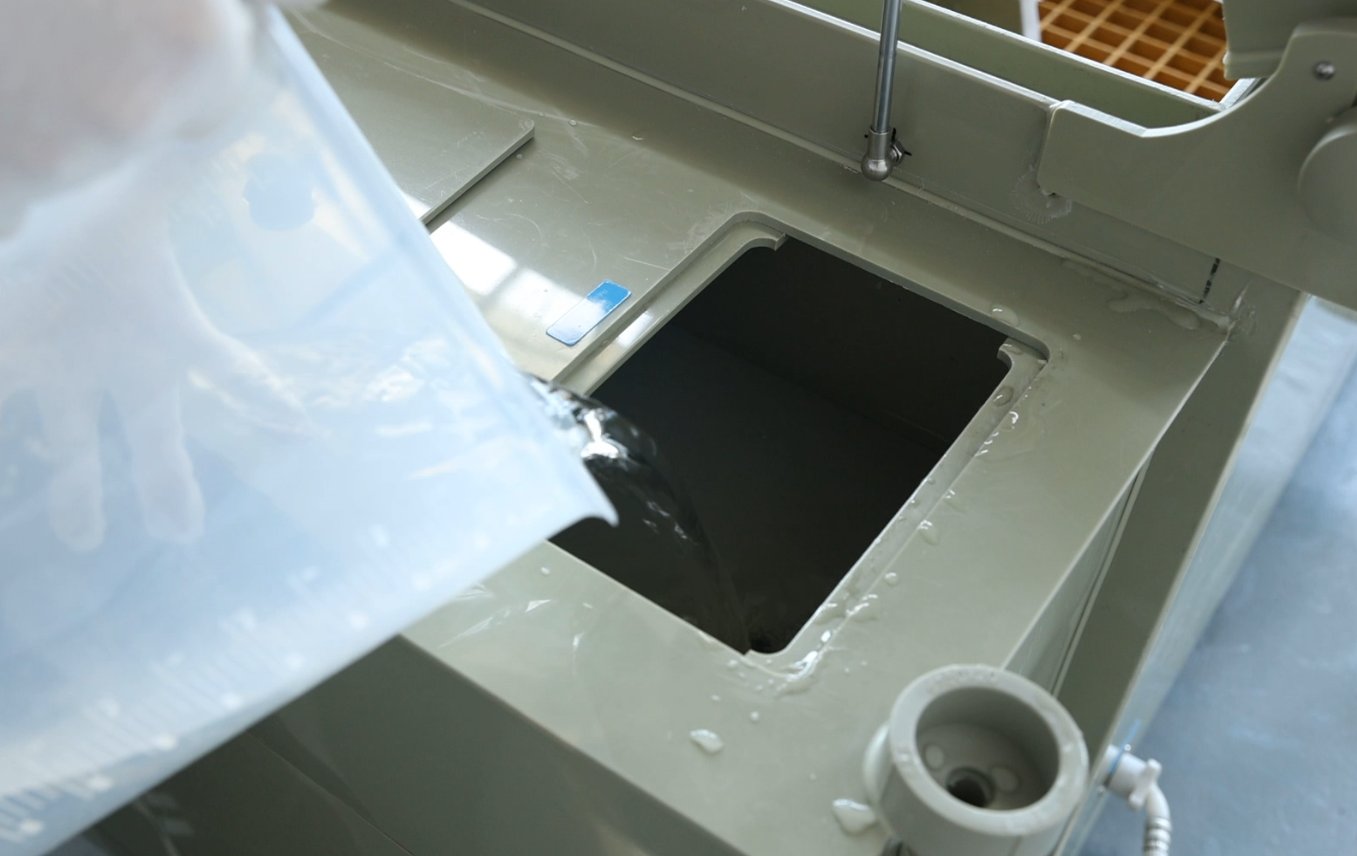
Monitor the water level in the “brine tank” on the touchscreen. When the “L” low-water indicator disappears, it indicates that the brine has reached the minimum operating level; however, if a long-term test is required (e.g., longer than 24 hours), you may continue to fill the brine tank until it is full (without exceeding the overflow level) to reduce the number of times you need to top off the brine during the test. Approximately 12 liters of brine is sufficient to power one spray tower for 24 hours of continuous spraying.
3.5 Sample Preparation and Loading
3.5.1 Sample Cleaning
Before testing, clean the sample surface to remove contaminants such as oil, dust, and fingerprints: Gently wipe the surface with a lint-free cotton swab dipped in anhydrous ethanol, or rinse with purified water and let it air dry. Avoid excessive wiping, which could damage the sample’s surface coating (such as electroplated or painted layers).
If there is a temporary protective coating on the sample surface (such as a protective film or rust-preventive paper), it must be completely removed to ensure that the sample surface comes into full contact with the salt spray.
3.5.2 Edge Protection
If the sample has cut edges, drilled holes, or marked areas (non-test areas), they must be sealed with high-temperature-resistant, salt-spray-resistant paint or tape to prevent galvanic corrosion in these areas, which could affect the accuracy of the test results.
It must be confirmed in advance that the sealing material does not react with the salt spray solution and will not contaminate the sample test area.
3.5.3 Holder Selection and Sample Placement
Choosing a Holder: Select a holder based on the sample’s size and shape—small samples can be suspended using round or triangular holders, while large or flat samples can be placed directly on the yellow mesh partition at the bottom of the mist chamber.
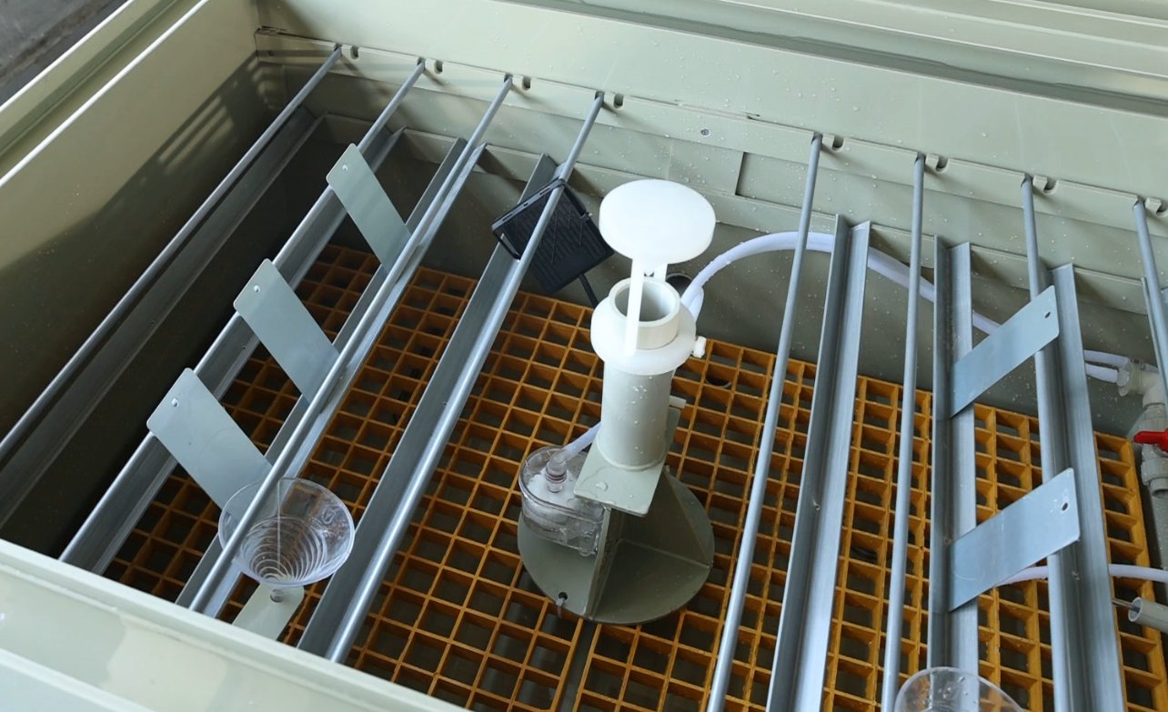
Cerințe de afișare:
Standard metal plate specimens must be placed at an angle of 15–25° (the angle can be adjusted using a stand) so that the test surface of the specimen is parallel to the direction of the salt spray flow, ensuring uniform coverage by the salt spray;
Sufficient distance must be maintained between samples (at least 1.5 times the largest dimension of the sample) to prevent the samples from coming into contact with one another or obstructing the salt spray, and condensation from the salt spray on one sample must not drip onto another sample;
The total volume of the sample must not exceed 3/5 of the chamber volume to avoid disrupting airflow circulation within the chamber, which could result in uneven temperature and salt spray distribution.
Except for the partitions and sample holders, the samples do not come into contact with any other components inside the test chamber.
3.6 Spray Pressure Adjustment
For instructions on using the touchscreen, refer to Chapter 4.
Close the test chamber lid. Go to the “Operation Settings” screen on the touchscreen, temporarily set the “Spray When Temperature Is Reached” function to “Off,” return to the main screen, and click “Run” to start the spray.
Adjust the spray pressure regulating valve on the front of the unit so that the front pressure gauge reads 1 kg/cm² (0.1 MPa), then observe the spray pattern from the nozzles inside the spray chamber: the spray should form a fine, uniform mist with no water droplets or interruptions, and the spray tower (if present) should cover the entire spray chamber.
After pre-spraying for 5 to 10 minutes, verify that the spray is uniform, with no water droplets and no interruptions in the spray.
4. Test Procedure (Key Touchscreen Operations)
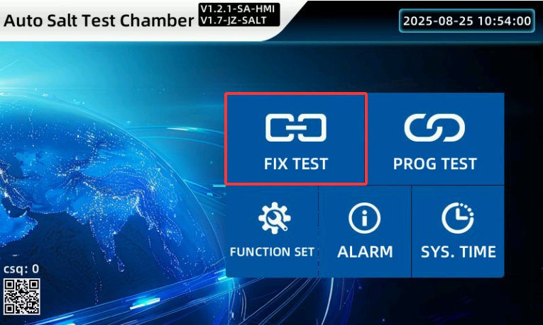
4.1 Setări de operare
Go to the “Operation Settings” screen:
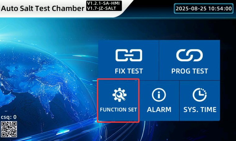
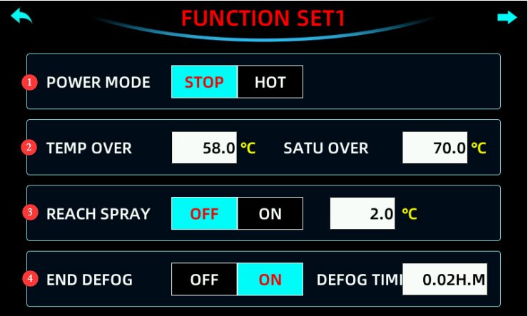
|
Conţinut |
Descrierea conținutului |
|
① Startup Method |
Configure power-on operations following a power outage. Stop: An operation that restores the system to the “Stop” state when power is restored after a power outage during operation. Hot Start: An operation that restores the system to the state it was in before the power outage when power is restored after a power outage during operation. |
|
② Over-Temperature Protection |
You can set the over-temperature alarm thresholds for the test chamber and the saturation tank; an alarm is triggered when the temperature exceeds these set values. |
|
③ Warm mist |
For the temperature-controlled spray function, select “On” or “Off.” When enabled, the unit will only activate the spray and start the timer when both the test chamber and the saturation tank reach a temperature within ±2 of the set value (this value can be adjusted; the factory default is ±2°C). |
|
④ End Defogging |
After setting the defogging time, turn on the defogging switch. The defogging process will start automatically once the test is complete and will end automatically when the set defogging time has elapsed. “0.02” represents 2 minutes; you can adjust the defogging time automatically based on the size of the test chamber. |
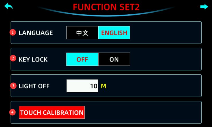
|
Conţinut |
Descrierea conținutului |
|
① Language Selection |
You can choose between Chinese and English. |
|
② Lock button |
When the lock is set to “On,” none of the parameter settings are available. |
|
③ Backlight Duration |
Screen Saver Time Settings: Setting this to 0 disables the screen saver. Please use a screen saver whenever possible to extend the life of the LCD backlight. |
|
④ Touchscreen Calibration |
If the touchscreen tap location does not match the actual location, you can perform a calibration using the touchscreen calibration function. If calibration is required, please contact LISUN. |
4.2 Calibration Test (FIX)
4.2.1 Introduction to the Calibration Test Screen
Fixed-value testing is suitable for tests conducted at a single temperature and with a single spray mode (such as conventional neutral salt spray testing).
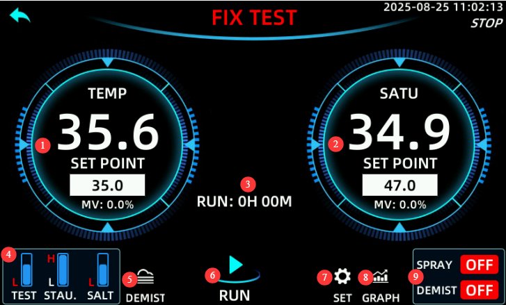
|
Conţinut |
notițe |
|
① Test Chamber Temperature |
Displays the current test temperature and the current test temperature setpoint. The default setting is 35°C (the standard test temperature for NSS/AASS). If a different temperature is required, it can be entered using the touchpad (the range is typically 10–60°C). |
|
② Saturated drum temperature |
Displays the current saturation temperature and the current saturation temperature setpoint. The default setting is 47°C (to ensure saturated air humidity and prevent cooling due to spray); this value must be 10–15°C higher than the test chamber temperature. |
|
③ Operating Time |
The elapsed time of the current test. If “Spray When Temperature Is Reached” is selected in “Operation Settings,” the elapsed time will not be recorded and will be displayed as 0 until the target temperature is reached. |
|
④ Water Level Display |
Water level display for the laboratory (test chamber), saturation tank, and brine tank. |
|
⑤ Manual Defogging |
Press this button to activate the defrost function. This is consistent with the “End Auto Defrost” setting in the operation menu. |
|
⑥ Run button |
Click to run the calibration test; click again to stop or pause the calibration test. |
|
⑦ Fixed-Value Settings |
Set the parameters for this fixed-value test. |
|
⑧Curve |
Click to view or export historical test curves. |
|
⑨ Spray and Defogging Status Display |
Displays the current spray and defogging statuses. |
4.2.2 Setting Parameters for Calibration Tests
To access the parameter settings screen:
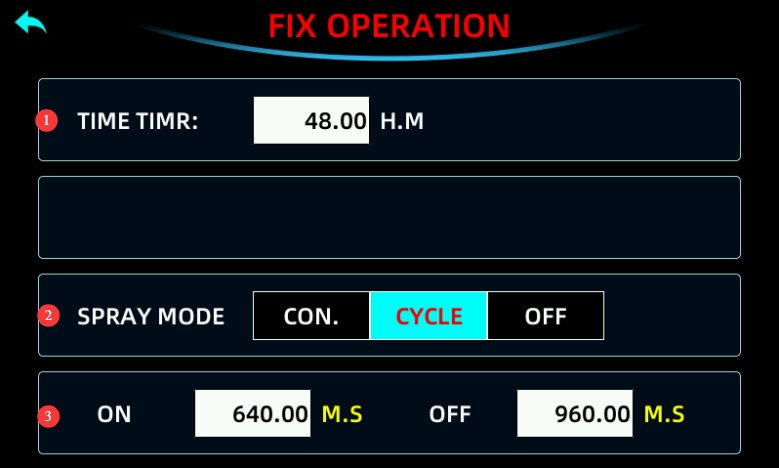
|
Conţinut |
notițe |
|
① Timer Duration |
Set the duration of this test, typically as a multiple of 24 hours (e.g., 24h, 48h, 72h). If set to 0, you must click the Stop button to end the test. |
|
② Spray Mode |
Continuous: Sprays continuously for the set duration; “Continuous” is typically selected for NSS testing; Cycle: Allows you to set spray and pause intervals, which alternate in a loop until the set duration is reached; Off: No spraying. |
|
③ Spray duration and pause duration |
If the spray mode is set to “Cycle,” this setting must be configured. |
4.3 Program Testing (PROGRAM)
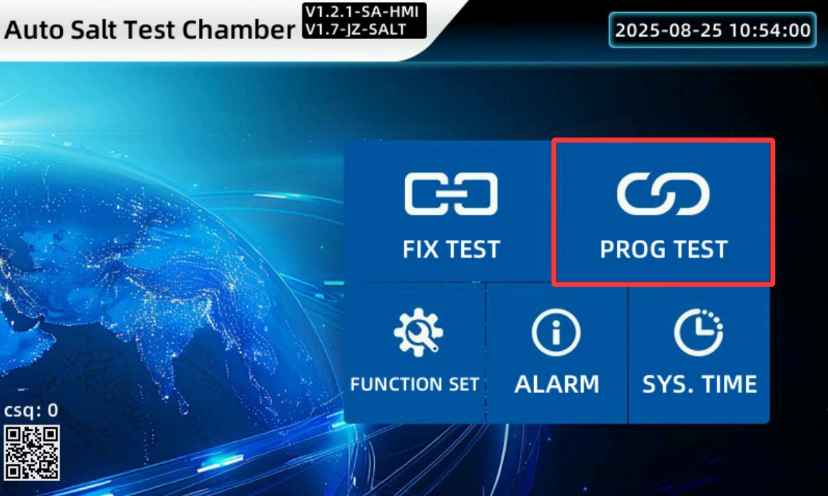
4.3.1 Introduction to the Program Test Screen
The program test is suitable for cyclic testing involving multiple temperature ranges and multiple spray modes (such as salt spray testing that simulates diurnal temperature fluctuations).
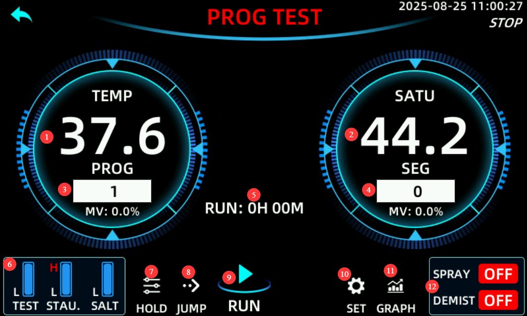
|
Conţinut |
notițe |
|
① Current temperature inside the test chamber. |
|
|
② Current saturated drum temperature. |
|
|
③ Current program number |
Click to select the program you want to run. |
|
④ The number of the currently running segment |
Each program has many test segments, and the segment number currently being executed is displayed. |
|
⑤ Current runtime. |
|
|
⑥ Water Level Display |
Water level display for the laboratory (test chamber), saturation tank, and brine tank. |
|
⑦ Maintain |
If you press this key while the program is running, the test chamber will continue to run the current test segment. |
|
⑧ Line Break |
During program execution, pressing this key will cause the test chamber to skip directly to the next section for testing. |
|
⑨ Run |
Click to run the program; click again to pause or stop it. |
|
⑩Settings |
Go to the program settings screen. |
|
11 Curbe |
Click to view or export historical test curves. |
|
12 Spray Defogging Mode |
Displays the current spray and defogging statuses. |
4.3.2 Introduction to the Program Settings Screen
To access the program settings screen:
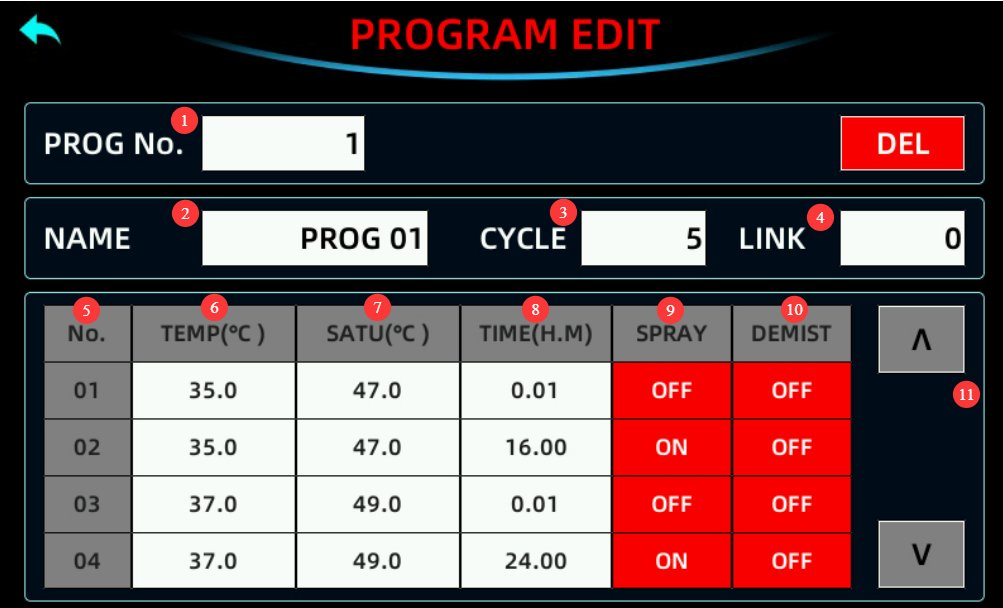
|
Conţinut |
notițe |
|
① Program Number |
Set the current program number, ensuring it does not conflict with existing program numbers. |
|
② Edit the name of the current program. |
|
|
③ Number of cycles |
If you do not want to loop, set it to 1. |
|
④ Program Linking |
If you want this program to automatically run another program once it finishes, enter the corresponding program number. If not, enter 0. |
|
⑤ The segment number contained in the current program. |
|
|
⑥ Set the temperature of the test chamber for the corresponding test section. |
|
|
⑦ Set the saturation tank temperature for the corresponding test section. |
|
|
⑧ Set the test duration for the corresponding test section. |
|
|
⑨ Spray Switch |
If spraying is required for this test section, switch the setting to ON. |
|
⑩ Defog Switch |
If defogging is required for this test section, switch it to ON. |
|
11 Move to the settings screen for the 4 segments before or after, in groups of 4 segments. |
Note: You must enable “Spray When Temperature Is Reached” in “Operation Settings.”
For the same temperature setting, you need to configure two adjacent test segments. The first segment is a transition segment, which should be set to 1 minute (it may actually take longer than one minute; the test chamber has a wait function that automatically advances to the next segment as soon as the set temperature is reached at the fastest possible speed). The second segment is the actual test duration.
If “End Defogging” is selected in “Operation Settings,” the defogging function does not need to be enabled for any test segments in the program. If “End Defogging” is not selected in “Operation Settings,” the final segment of the program can be set to defogging.
4.4 Monitorizarea procesului de testare
4.4.1 Monitorizarea temperaturii
Monitor the temperature of the test chamber and the saturated bucket displayed on the touchscreen in real time. The temperature will rise slowly to the target temperature; once it stabilizes, fluctuations should not exceed ±1°C. If the temperature is abnormal, stop operation and refer to Chapter 6 for troubleshooting.
4.4.2 Water Level Monitoring
Check the water levels in the laboratory (test chamber), saturation tank, and brine tank regularly. You may monitor them based on the following guidelines:
The water inside the test chamber is not consumed, so low-water-level alarms rarely occur under normal circumstances, unless the test chamber is vibrating or shaking;
The water in the saturation tank is used to pressurize the spray system and will be consumed; please refill the tank as described in Section 3.3.2. If you need to add water manually, tap the touchscreen to pause the test. After adding water, tap to resume the test. If automatic water replenishment is enabled, the test will automatically pause when the water level in the saturation tank drops to the “L” low-water alarm level. The system will then automatically replenish the water, and the test will resume automatically upon completion without requiring manual intervention;
The brine in the brine tank is used for the spray test and will be consumed; please replenish the brine as described in Section 3.4.2.
4.4.3 Spray Monitoring
Observe the spray pattern through the glass door of the mist chamber to ensure that the spray is uniform and uninterrupted. If any abnormalities are detected (such as a decrease in spray volume or water dripping from the nozzle), pause the test to check whether the nozzle is clogged or if the air pressure is stable.
4.4.4 Înregistrarea datelor
Record the test duration, mist chamber temperature, saturation chamber temperature, brine level, and spray status every 2 to 4 hours; you can also export all historical data after the test is complete.
4.5 End of the Test and Shutdown
4.5.1 Stopping Spraying and Defogging
Timed End: If a test duration has been set, the equipment will automatically stop spraying when the time elapses and enter the defogging mode (when “End Defogging” is enabled). Once defogging is complete, the touchscreen will display “Test Complete.”
Manual Stop: If you need to stop the test early, tap the “Stop” button on the touchscreen. The equipment will stop spraying. You can choose whether to activate the defogging function (tap the “Manual Defogging” button). Once the salt fog has been expelled from the chamber, turn off the “Manual Defogging” button before proceeding with subsequent operations.
4.5.2 Data Organization and Sample Retrieval
Data Organization: Record the total test duration, actual temperature curves, and any anomalies (such as mid-test water replenishment or alarms); export and save historical data (if available); and organize the test record forms.
Removing the Sample: After the defogging process is complete, let the sample sit for 5 minutes. Wear acid- and alkali-resistant gloves, open the chamber door, and carefully remove the sample (taking care to prevent salt deposits from falling off the sample’s surface). Place the sample on a clean tray and label it with the relevant information (such as the test number and test duration).
4.5.3 Oprirea echipamentului
Turn off the air compressor or disconnect the air intake hose, and turn off the power to the test chamber.
5. Post-Test Processing
5.1 Pregătirea probei
5.1.1 Sample Cleaning and Drying
Cleaning: In accordance with the test standard requirements, gently rinse the sample surface with purified water (or distilled water) at a temperature of ≤38°C to remove residual salt deposits. Avoid vigorous rinsing, which could damage the sample’s corrosion products (such as rust layers or oxidation layers); If permitted by the standard, a small amount of neutral detergent (such as dish soap) may be applied to remove stubborn salt deposits, followed by thorough rinsing with purified water.
Drying: After washing, use clean, degreased cotton or filter paper to blot the moisture from the sample’s surface, or place the sample in a ventilated drying cabinet at room temperature (without heat) to air-dry. Avoid direct sunlight or high-temperature drying to prevent changes in the sample’s surface condition.
5.1.2 Evaluarea probei
Visual Inspection: Examine the sample surface for signs of rust, discoloration, coating peeling, blistering, etc. Record the area affected by corrosion and the severity of corrosion (e.g., mild, moderate, severe). Take photographs for future comparison.
Performance Testing: Depending on the objectives of the test, conduct follow-up performance tests on the samples (such as adhesion testing, impact resistance testing, and electrical performance testing) to evaluate the impact of salt spray corrosion on the samples’ performance, and compile an evaluation report.
5.2 Equipment Cleaning
5.2.1 Cleaning the Fog Chamber
Rinse the inner walls of the mist chamber, the spray tower, the mist collector, and the mesh partitions with purified water to remove residual salt deposits and scale. For stubborn stains, gently scrub with a soft-bristled brush dipped in a neutral detergent, then rinse thoroughly with purified water.
Clean the temperature probe and the surface of the heating tube: Wipe the temperature probe with a soft cloth to remove any salt spray buildup; if there is scale on the surface of the heating tube, soak it in a citric acid solution (5% concentration) for 10–15 minutes, then rinse with clean water. Avoid scraping the heating tube with hard objects(to prevent damage to the coating).
5.2.2 Cleaning the Saturation Tank
Open the drain valve on the saturation tank (located at the bottom of the test chamber), drain out any remaining water, close the drain valve, then fill the tank with a 5% citric acid solution and let it soak for 20–30 minutes (to remove scale from the inner walls of the tank). Next, drain the solution and rinse the tank 2–3 times with purified water to ensure no citric acid residue remains.
Cleaning the saturated tank liquid level sensor: Use a soft cloth dipped in purified water to wipe the sensor probe, removing any scale buildup to ensure accurate liquid level detection.
5.2.3 Cleaning the Brine Tank and Nozzles
Brine Tank: Rinse the inside walls of the tank with purified water to remove any residual brine and sediment. If there are salt crystals, soak the tank in warm water, then scrub them off. After rinsing thoroughly, let the tank air dry.
Nozzle Cleaning: Remove the nozzle and gently clear the small holes in the nozzle with a thin copper wire (diameter ≤ 0.5 mm), taking care not to apply excessive force that could damage the nozzle; Soak the nozzle in a 5% citric acid solution for 15 minutes to remove scale, then rinse thoroughly with purified water, let it air dry, and reinstall it (ensuring the small hole in the glass tube is properly aligned); If the nozzle is cracked, the orifice is deformed, or it fails to spray properly even after cleaning, replace it with a spare nozzle.
5.3 Cerințe privind depozitarea pe termen lung
5.3.1 Preparations Before Storage
If the equipment will not be used for an extended period (more than 1 month), take the following steps:
Turn Off Power and Air Supply: Disconnect the equipment from the power source, unplug the air hose from the air compressor, and turn off the air compressor’s power;
Thoroughly clean the equipment: Follow the steps in “5.2 Equipment Cleaning” to clean the fog chamber, saturation tank, salt water tank, and nozzles, ensuring no salt residue remains;
Drain all liquids: Open the drain valve to remove any residual water from the components, and use compressed air to dry the interior (to prevent moisture and rust);
Protecting Components: Cover the equipment with a dust cover to prevent dust from entering.
5.3.2 Maintenance During Storage
Storage conditions must meet the requirements specified in Section 2.3.1;
Power on once a month: Turn on the power to the equipment and let it run for 30 minutes (without adding water or brine) to prevent electrical components (such as capacitors and contactors) from deteriorating;
Inspect once a month: Open the dust cover and check the interior of the equipment for rust or mold; if any is found, clean and dry it immediately. Check the hoses for signs of aging and ensure the connections are secure.
6. Depanarea problemelor comune
If the device malfunctions, please refer to the following common problems and solutions:
|
Probleme comune |
Cauze posibile |
Procedură |
|
Fog Chamber / Saturation Tank Not Heating |
1. Insufficient liquid level; 2. Burnt-out heating element; 3. Faulty temperature controller; 4. Damaged temperature sensor |
1. Top off the fluid until the level indicator turns green; 2. Turn off the power and check the resistance of the heating element (which should normally be several tens of ohms); if it is burned out, replace it; 3. Restart the unit; if it still does not respond, contact customer service to have the controller repaired; 4. Check the probe wiring; if damaged, replace it. |
|
Fara spray |
1. Insufficient brine; 2. Clogged nozzle; 3. Air leak (e.g., disconnected air hose, damaged solenoid valve); 4. Improper air pressure adjustment |
1. Refill with saline solution; 2. Clean the nozzle (see 5.2.3); 3. Check the air hose connections and replace any damaged solenoid valves; 4. Readjust the air pressure (0.2 MPa at the back, 1 kg/cm² at the front) |
|
The temperature cannot reach the set point |
1. Insufficient heating element power; 2. Liquid level sensor malfunction (abnormal liquid level display); 3. Ambient temperature is too low; 4. Poor door seal |
1. Check the heating element’s wattage and replace it with a compatible one; 2. Clean or replace the liquid level sensor; 3. Adjust the ambient temperature (e.g., turn up the heat); 4. Check the water level in the sealing tank and top it off to the standard level |
|
Nicio modificare a temperaturii |
1. The equipment is vibrating; 2. Momentary fluctuations in temperature readings have triggered the protective mechanism. |
1. The equipment must be in a stable state during operation; 2. Stop the test, let it sit for about 1 minute, and then restart the test. |
|
The front pressure gauge cannot be adjusted to a higher reading |
1. The manual water fill valve on the pressure tank is not closed; 2. The nozzle air hose has come loose or is cracked; 3. The spray solenoid valve is damaged |
1. Close the manual water fill valve; 2. Replace or reconnect the air hose; 3. Replace the solenoid valve |